
Short Engineering Answer
Heat set inserts fail in robotics assemblies when the printed fastening structure cannot maintain preload, torque resistance, axial retention, or boss support under repeated motion, service access, vibration, and changing load direction.
Robotics parts often experience more than simple static screw loading. They may be assembled and disassembled many times, exposed to motor vibration, loaded by moving joints, or stressed by brackets, sensors, covers, and actuator mounts. These conditions can weaken the plastic-to-insert interface over time.
The metal insert is rarely the only issue. Most failures come from the surrounding printed boss, screw engagement length, material behavior, layer orientation, installation quality, and repeated assembly load.
A reliable robotics insert joint must be designed as a serviceable, load-bearing fastening structure, not only as a threaded hole.
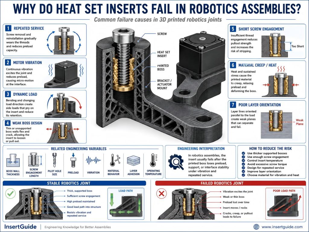
Root Causes
Repeated Service and Maintenance
Robotics assemblies are often opened, adjusted, repaired, or upgraded.
Each screw removal and reinstallation transfers torque into the insert and surrounding printed plastic. Over time, this can reduce mechanical locking around the insert, especially if the boss is thin, the pilot hole is loose, or the material creeps under preload.
The insert may still look seated, but the joint may feel less tight or less consistent after repeated service cycles.
Dynamic Loads From Moving Parts
Robotics parts often carry loads that change direction.
Brackets, actuator mounts, sensor arms, grippers, and moving frames may experience bending, twisting, impact, or cyclic motion. These loads can stress the insert joint in ways that a static enclosure does not.
If the insert load path is not supported by enough boss material, the joint may loosen, spin, crack, or pull out over time.
Motor Vibration
Motors, servos, gearboxes, and belts can introduce vibration into robotics assemblies.
Vibration can reduce joint stability when preload is already weak or when the boss cannot resist dynamic load. If the insert interface has small movement, vibration can make that movement grow over time.
This can lead to insert loosening, screw preload loss, boss fatigue, or reduced torque resistance.
Weak Boss Geometry
A heat set insert depends on the boss around it.
In robotics assemblies, designers may reduce wall thickness to save weight or fit compact mechanisms. But a thin, tall, unsupported, or edge-adjacent boss may not provide enough radial support around the insert.
A weak boss may deform under screw preload, crack under bending load, or allow the insert to rotate during tightening.
Boss geometry should be designed around the expected load path, not only around insert diameter.
Insufficient Screw Engagement
Short screw engagement can reduce joint reliability in robotics assemblies.
If the screw engages too few threads in the insert, the load is concentrated over a smaller area. This makes the joint more sensitive to torque variation, vibration, repeated assembly, and side loading.
Enough screw engagement helps distribute load through the insert and into the boss, improving preload stability and long-term reliability.
Material Creep or Brittleness
Different printed materials fail differently in robotics applications.
PETG may creep or deform under sustained preload, especially near warm motors or enclosed electronics. PLA may hold shape well but crack more easily under stress concentration or impact. ABS or engineering materials may perform better in some dynamic applications, but still require proper boss geometry and installation control.
Material choice should match the real load conditions: motion, vibration, heat, service cycles, and screw preload.
Layer Orientation and Load Direction
FDM printed parts are directionally strong.
If a robotics insert joint is loaded across weak layer lines, the boss may crack or delaminate even if the insert is installed correctly. This is especially important in brackets, arms, hinges, grippers, and actuator mounts where bending loads may peel layers apart.
Heat set inserts improve thread durability, but they do not remove the anisotropic strength limits of printed plastic.
Related Engineering Variables
Heat set insert reliability in robotics assemblies depends on several connected variables:
- Number of service cycles
- Screw preload
- Tightening torque
- Screw engagement length
- Boss wall thickness
- Boss stiffness
- Pilot hole size
- Insert depth
- Material creep
- Motor vibration
- Dynamic load direction
- Bending load
- Impact load
- Layer adhesion
- Print orientation
- Operating temperature
- Installation temperature
These variables should be evaluated together. A heat set insert that works in a static cover may fail in a robotic actuator bracket because the load path, vibration, and service frequency are different.
Robotics fastening reliability is a system problem involving insert, boss, screw, material, and motion.
Engineering Interpretation
Heat set insert failure in robotics assemblies is usually a dynamic load and serviceability problem.
The failure may appear as:
- Insert loosening from preload loss
- Insert spin from reduced torque resistance
- Pull-out from axial or bending load
- Boss cracking from stress concentration
- Layer separation from poor print orientation
- Torque loss from repeated assembly or material creep
These failures often interact.
For example, repeated maintenance may reduce preload. Motor vibration may then increase interface movement. A thin boss may start to deform, and eventually the insert may spin or pull out.
This is why robotics parts need insert joints designed for repeated use and dynamic loading. The insert alone provides durable threads, but the printed structure must carry the actual loads.
How to Reduce the Risk
To reduce heat set insert failure in robotics assemblies:
- Design bosses for dynamic load, not only static screw holding.
- Use enough boss wall thickness around the insert.
- Avoid tall, thin, unsupported bosses.
- Use enough screw engagement length.
- Use the correct pilot hole size for the printed material.
- Control installation temperature.
- Avoid excessive screw torque.
- Choose material based on vibration, creep, heat, and impact.
- Improve layer orientation around loaded insert joints.
- Support high-load bosses with ribs or surrounding structure.
- Design serviceable joints for repeated screw removal.
- Reduce vibration transfer where possible.
- Avoid loading inserts across weak layer lines.
A strong robotics insert joint comes from a supported fastening structure. The screw, insert, boss, material, and load path must work together.
Related InsertGuide Pages
- Why Do Heat Set Inserts Fail Under Vibration?
- Why Does Repeated Assembly Weaken Heat Set Inserts?
- Why Do Threaded Inserts Loosen After Repeated Screw Removal?
- Why Does Screw Preload Drop in 3D Printed Insert Joints?
- Screw Engagement Length for Heat Set Inserts in 3D Printed Parts
- Torque Resistance of Heat Set Inserts in 3D Printed Parts
- Layer Adhesion and Heat Set Insert Strength in 3D Printed Parts
- How to Design Bosses for Heat Set Inserts
- Heat Set Inserts for Repeated Assembly in 3D Printed Parts
FAQ
Are heat set inserts good for 3D printed robotics parts?
Yes. Heat set inserts are useful in robotics parts because they provide stronger and more durable threads than printed plastic. However, the boss, screw engagement, material, and print orientation must be designed for dynamic loads and repeated service.
Why do inserts loosen in robotics assemblies?
Inserts loosen in robotics assemblies when repeated service, vibration, preload loss, weak boss support, material creep, or short screw engagement weakens the plastic-to-insert interface.
Can motor vibration damage heat set insert joints?
Motor vibration can accelerate failure if the insert joint already has weak preload, poor boss support, insufficient screw engagement, or poor layer orientation. Vibration usually amplifies an existing design weakness.