
If your heat set inserts are spinning, cracking PLA, or not holding properly, the most common cause is incorrect hole size selection.
This guide explains the recommended hole sizes for M2–M5 heat set inserts in PLA and PETG 3D printed parts.
Heat set insert hole size is one of the most important design decisions when using heat set inserts in 3D printed parts. A heat set insert does not work by simply sitting inside a hole. It works when heated plastic flows around the insert’s external features and locks the insert in place after cooling.
If the hole is too large, the insert may not have enough plastic to grip. If the hole is too small, An undersized hole can create excessive radial stress during installation and increase the risk of boss cracking around heat set inserts, especially in PLA parts. the printed part may crack, deform, or force melted plastic into the internal thread. SPIROL’s design guidance explains that larger holes reduce insert performance, while smaller holes can create stress, cracking, flash, and installation difficulty.
For 3D printed parts, the best hole size depends on the insert geometry, printed material, printer calibration, hole orientation, wall thickness, and installation method. There is no single universal hole size for every M3, M4, or M5 insert.
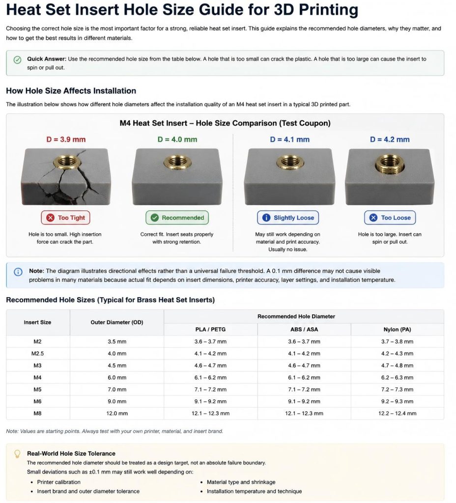
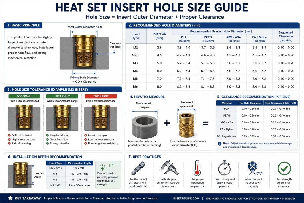
Why Hole Size Matters
The hole is not just an empty space for the insert. It is part of the fastening structure.
A correct hole size helps:
- guide the insert during installation
- allow controlled plastic displacement
- improve torque resistance
- improve pull-out resistance
- reduce cracking around the boss
- prevent melted plastic from entering the thread
- keep the insert straight and seated correctly
A poor hole size can make even a good insert fail.
Heat set inserts rely on plastic conforming to the external features of the insert. SPIROL describes insert retention as being created when enough plastic is displaced to fill the insert’s external features and then solidifies around them.
Oversized pilot holes can increase the risk of heat set insert spin because the surrounding plastic cannot fully resist rotational torque during screw tightening.
M3 Heat Set Insert Hole Size: Quick Answer
For most M3 heat set inserts used in 3D printed parts, the starting hole size is usually about 4.0 mm to 4.2 mm, depending on the insert’s outer diameter, knurl geometry, and the printed material.
This is not a universal rule. The correct hole size should be based on the actual insert datasheet, the material being printed, and whether the insert is designed for PLA, PETG, ABS, nylon, or carbon fiber filled materials.
A good M3 insert hole should allow the insert to melt into the plastic without excessive force, while still leaving enough surrounding material for pull-out strength and torque resistance.
| Insert size | Typical starting hole range | Notes |
|---|---|---|
| M3 heat set insert | 4.0–4.2 mm | Check insert OD and material behavior |
| M4 heat set insert | 5.0–5.6 mm | Depends more strongly on insert series |
| M5 heat set insert | 6.0–6.8 mm | Boss wall thickness becomes more important |
Direct Answer: What Hole Size Should You Use?
The hole should usually be slightly smaller than the outer retention features of the heat set insert, but the exact size should come from the insert manufacturer’s drawing or a printed test coupon.
A practical rule is:
Do not design the hole only from the screw size.
Design the hole from the insert’s outer diameter and external geometry.
For example, an M3 insert only tells you that the internal thread fits an M3 screw. It does not tell you the correct printed hole diameter. Two M3 heat set inserts from different suppliers can have different outer diameters, lengths, knurl patterns, and recommended hole sizes.
Step-by-Step Guide
1. Check the Insert Drawing First
Before modeling the hole in CAD, check the insert supplier’s dimensional drawing.
Look for:
- internal thread size
- insert length
- maximum outer diameter
- minimum outer diameter
- knurl diameter
- flange diameter
- taper direction
- recommended hole diameter
- recommended hole depth
If the supplier provides a hole size, use it as the starting point. Then verify it with a test print.
McMaster lists many types of heat-set threaded inserts, including tapered, straight, and any-orientation styles. Different insert types are not designed for the same hole geometry.
2. Measure the Actual Insert
Do not rely only on the product name.
Use calipers to measure:
- outer diameter at the largest knurl
- outer diameter at the smallest end
- insert length
- flange diameter, if present
- thread depth
This is especially important when buying generic brass inserts, because the listed size may refer only to the internal thread.
A part labeled as “M3 insert” may still need a different hole than another M3 insert.
3. Start With a Test Hole Matrix
For 3D printing, the safest method is to print a small test coupon before printing the final part.
A simple test coupon can include several holes with small diameter differences:
| Test Hole | Purpose |
|---|---|
| Manufacturer recommended size | Baseline test |
| Recommended size minus 0.1 mm | Tighter fit test |
| Recommended size plus 0.1 mm | Easier installation test |
| Recommended size plus 0.2 mm | Check if insert becomes loose |
| Material-specific adjusted size | Used when PLA, PETG, ABS, nylon, or resin behaves differently |
The goal is not just to see whether the insert goes in. The goal is to check whether it stays straight, sits flush, grips the plastic, and resists torque after cooling.
Typical Starting Hole Sizes
| Insert Size | Recommended Hole Diameter |
|---|---|
| M2 | 3.1 mm |
| M2.5 | 3.8 mm |
| M3 | 4.2 mm |
| M4 | 5.6 mm |
| M5 | 6.8 mm |
| M6 | 8.2 mm |
Actual hole size requirements may vary depending on printer calibration, material shrinkage, insert manufacturer tolerances, and installation conditions.
4. Remember That Printed Holes Often Come Out Smaller
3D printed holes often print smaller than their CAD diameter. This happens because of extrusion width, slicer compensation, material flow, printer calibration, and the way circular perimeters are generated.
CNC Kitchen notes that printed holes commonly come out smaller than expected, and CAD hole size may need to be modeled larger to achieve the intended printed diameter.
This means a 4.0 mm hole in CAD may not become a true 4.0 mm hole in the printed part.
Always verify the printed hole with a real test part.
5. Match Hole Size to Insert Geometry
Different insert shapes need different hole logic.
| Insert Geometry | Hole Design Consideration |
|---|---|
| Tapered insert | Hole may need to match the taper direction |
| Straight insert | Hole diameter must be consistent along the depth |
| Knurled insert | Hole must allow plastic to flow into knurl features |
| Flanged insert | Top clearance and seating surface matter |
| Short insert | Depth tolerance is more sensitive |
| Long insert | Alignment and boss strength become more important |
Tapered inserts are often easier to align during installation. McMaster describes tapered heat-set inserts as easier to guide into a hole than straight inserts.
6. Design the Hole Deeper Than the Insert
The hole should usually be deeper than the insert length.
During installation, softened plastic needs somewhere to move. If the hole is too shallow, plastic may be pushed into the internal thread or the insert may not seat flush.
SPIROL’s design guidance states that holes for heat or ultrasonic inserts should always be deeper than the insert length, with a recommended minimum depth of insert length plus two thread pitches.
A practical design rule is:
Hole depth = insert length + clearance for displaced plasticDo not let the screw bottom out in the hole. If the screw bottoms out before clamping the assembly, it can push the insert upward or damage the printed part.
7. Add a Small Chamfer or Lead-In
A small chamfer at the top of the hole helps the insert start straight.
This is especially useful when installing inserts by hand with a soldering iron.
A chamfer can help:
- guide the insert into the hole
- reduce edge damage
- reduce plastic shaving
- improve alignment
- make installation more consistent
Do not make the chamfer too large. If the chamfer removes too much material around the top of the hole, the insert may lose support near the surface.
8. Consider the Printed Material
The same hole size can behave differently in different materials.
| Material | Hole Size Behavior |
|---|---|
| PLA | Easy to melt, but boss deformation is common |
| PETG | Tougher, but plastic flow and stringing can be more noticeable |
| ABS | More heat tolerant, often easier to install cleanly |
| ASA | Similar to ABS, useful for outdoor parts |
| Nylon | Flexible and tough, but hole control is important |
| Resin | Brittle, may crack if the hole is too tight |
| Carbon fiber filled filament | Stiffer, but may crack or split if the boss is weak |
PLA often needs careful heat control because it softens quickly. PETG may tolerate installation better, but it can produce more visible plastic flow around the insert. Resin parts need extra caution because they do not behave like melted thermoplastic filament parts.
9. Consider Wall Thickness Around the Hole
A correct hole diameter is not enough if the boss wall is too thin.
The printed boss must have enough surrounding material to resist:
- installation pressure
- thermal softening
- screw tightening torque
- pull-out load
- repeated assembly
- side loading
If the insert is close to the edge of the part, the hole may crack even if the diameter is technically correct.
A hole size guide should always be used together with boss design and wall thickness rules.
10. Test the Hole After Cooling
Do not judge the hole immediately after installation.
Let the insert cool before testing. The plastic needs time to solidify around the insert’s external features.
After cooling, test:
- whether the screw threads smoothly
- whether the insert remains flush
- whether the insert spins under torque
- whether the boss cracks
- whether the insert pulls out under load
- whether plastic entered the internal thread
A hole that feels good during installation may still fail during tightening.
Common Mistakes
Mistake 1: Using a Generic M3 Hole Size
There is no universal M3 heat set insert hole size. The correct hole depends on the insert’s outer geometry, not only the internal thread.
Mistake 2: Making the Hole Too Large
An oversized hole may make installation easier, but it reduces the amount of plastic available to flow into the insert features. This can cause spinning or pull-out.
Mistake 3: Making the Hole Too Small
An undersized hole can crack the boss, deform the printed part, or force melted plastic into the thread.
Mistake 4: Ignoring Printed Hole Shrinkage
If your printer produces undersized holes, the actual printed hole may be smaller than the CAD model. Test before final production.
Mistake 5: Making the Hole Too Shallow
A shallow hole leaves no room for displaced plastic. This can block the thread or prevent the insert from seating correctly.
Mistake 6: Forgetting the Screw Length
The screw should engage the insert without bottoming out in the hole. If the screw is too long, it can push against the bottom of the hole or damage the assembly.
Mistake 7: Testing Only Fit, Not Strength
An insert that fits into the hole is not automatically strong. Always test torque resistance and pull-out behavior after cooling.
Engineering Notes
- Hole size should be based on insert geometry, not just screw size.
- The manufacturer’s recommended hole size should be treated as a starting point.
- Printed hole accuracy depends on printer calibration, material, slicer settings, and orientation.
- Hole depth is just as important as hole diameter.
- A slightly loose insert may install cleanly but fail under torque.
- A very tight hole may feel strong but crack the boss.
- Small test coupons are the safest way to verify hole size.
- For repeated assembly, boss design and screw engagement matter as much as hole diameter.
- A correct hole size cannot compensate for weak wall thickness.
Failure Examples
Example 1: Insert Spins After Installation
Likely causes:
- hole too large
- not enough plastic flow
- weak knurl engagement
- insert overheated and disturbed the hole
- boss wall too thin
Example 2: Boss Cracks During Installation
Likely causes:
- hole too small
- brittle material
- poor layer orientation
- excessive insertion force
- boss diameter too small
Example 3: Insert Does Not Sit Flush
Likely causes:
- hole too shallow
- insert misaligned
- plastic trapped under the insert
- installation stopped too early
- flange or knurl geometry not considered
Example 4: Screw Is Hard to Thread
Likely causes:
- melted plastic entered the thread
- screw is too long
- insert is tilted
- internal thread was damaged during installation
- hole depth is insufficient
Example 5: Insert Pulls Out Under Load
Likely causes:
- hole too large
- insert too short
- not enough surrounding plastic
- weak layer direction
- load direction not considered during design
Related Engineering Factors
Hole size is one of the most important variables in heat set insert performance for 3D printed parts.
Important related engineering factors include:
- printed hole tolerance
- insert outer diameter
- interference fit
- material shrinkage
- boss wall thickness
- insert spinning resistance
- pull-out strength
- installation temperature
- printer calibration accuracy
- layer compression during installation
Even small changes in hole diameter can significantly affect insert retention, installation quality, and long-term assembly reliability.
Related engineering guides:
- How to Choose Heat Set Inserts for 3D Printed Parts
- How to Design Bosses for Heat Set Inserts
- Why Heat Set Inserts Fail in 3D Printed Parts
- Pull-Out Strength of Heat Set Inserts in 3D Printed Parts
- Torque Resistance of Heat Set Inserts in 3D Printed Parts
- Heat Set Insert Installation Temperature for 3D Printed Parts
FAQ
What hole size should I use for heat set inserts?
Use the insert manufacturer’s recommended hole size as the starting point, then verify it with a printed test coupon. The correct hole size depends on the insert’s outer diameter, knurl pattern, material, and print accuracy.
Is there a standard M3 heat set insert hole size?
No single M3 hole size works for every insert. M3 only defines the internal thread. The printed hole should be based on the insert’s external geometry.
Should the hole be smaller than the heat set insert?
Usually, the hole is slightly smaller than the insert’s outer retention features so the heated insert can displace plastic and lock into place. However, the exact amount depends on the insert design and material.
How deep should a heat set insert hole be?
The hole should usually be deeper than the insert length. This gives displaced plastic somewhere to move and helps prevent blocked threads or poor seating.
Why do heat set inserts spin in the hole?
Inserts often spin when the hole is too large, the plastic did not flow into the insert’s knurls, or the boss wall is too weak to resist torque.
Why do heat set inserts crack the printed part?
Cracking usually happens when the hole is too small, the material is brittle, the boss wall is too thin, or too much force is used during installation.
Should I drill the hole after printing?
Drilling can improve hole accuracy, but it may remove printed wall structure and reduce plastic available for insert retention. For functional parts, test both printed and drilled holes before final use.
Do PLA and PETG need different hole sizes?
They may. PLA softens quickly and can deform, while PETG may produce more plastic flow. The same CAD hole can behave differently in different materials.
Should I add a chamfer to the hole?
A small chamfer can help guide the insert and improve alignment. Avoid a large chamfer that removes too much support around the insert.
How do I test heat set insert hole size?
Print a small test coupon with several hole diameters, install the insert, let it cool, then test screw engagement, torque resistance, pull-out behavior, and cracking.
Conclusion
Heat set insert hole size is not a fixed number. It is a design decision based on insert geometry, printed material, hole depth, wall thickness, printer accuracy, and installation method.
The safest approach is to start with the insert manufacturer’s recommended hole size, measure the actual insert, print a small test coupon, and verify the result after cooling.
For 3D printed parts, a good hole does more than hold the insert in place. It creates a controlled plastic flow zone that allows the insert to become part of the structure.
A strong heat set insert joint starts with a correctly designed hole.
For more common engineering questions, see the 3D Printing Fastening FAQ.
Explore More Engineering References
Explore additional engineering guides, fastening references, insert recommendations, and 3D printed assembly knowledge across the InsertGuide engineering network.
Related Engineering Guides
- Ngineering Guides for 3D Printed Fastening
- 3D Printing Fastening FAQ
- 3D Printed Fastening Applications
- How to Choose Heat Set Inserts for 3D Printed Parts
- How to Design Bosses for Heat Set Inserts
- PLA vs PETG vs ABS for Threaded Inserts
- Why Heat Set Inserts Fail in 3D Printed Parts
- Pull-Out Strength of Heat Set Inserts in 3D Printed Parts
- Torque Resistance of Heat Set Inserts in 3D Printed Parts
- Layer Adhesion and Heat Set Insert Strength in 3D Printed Parts
- Heat Set Insert Installation Temperature for 3D Printed Parts
- Screw Engagement Length for Heat Set Inserts in 3D Printed Parts
Additional Heat Set Insert Hole Size FAQ
Is the pilot hole determined only by the M2, M3, M4, or M5 thread size?
No. M2, M3, M4, and M5 describe the internal screw thread, not the insert’s outside diameter or knurl geometry. Use the insert manufacturer’s hole recommendation as the starting point and verify the actual fit with the specific insert series.
Why does the same CAD hole fit differently in PLA and PETG?
PLA and PETG print with different shrinkage, extrusion flow, stiffness, and heat response. Measure the cooled printed hole rather than relying only on the CAD diameter. Calibrate separate test coupons when switching material, printer, nozzle, or print orientation.
What hole-size tolerance steps should I test for a heat set insert?
Start with the manufacturer’s recommended pilot hole and test nearby diameters in 0.1 mm steps. Stop using a tighter sample if the insert will not self-center or requires excessive installation force, because an undersized hole can cause PLA cracking during installation. Test after the insert has fully cooled.
Why does a heat set insert fall out after the plastic cools?
The hole may be oversized, the plastic may not have flowed into the knurls, or the insert geometry may not match the pilot hole. A joint that feels tight while hot can become loose after cooling. Check the actual printed diameter and review the common causes of an insert falling out.
Why does a heat set insert go crooked when the hole diameter looks correct?
The printed hole may be oval, tapered, too shallow, or missing a controlled lead-in. Uneven heating and off-axis pressure can also tilt the insert before the plastic solidifies. Compare the installation against these causes of an insert becoming crooked after installation.
Related Decision Resources
When selecting hole size in real applications, consider best heat set insert options, the exact M3 insert geometry, and short vs long insert length after the pilot hole tolerance, material behavior, and pull-out requirements are defined.
Heat Set Insert Knowledge Hub
Use this section to move from the general hole size guide into size-specific hole references, material behavior, installation process control, and common failure diagnosis.
Size Guides
- M2 Heat Set Insert Hole Size for 3D Printed Parts
- M2.5 Heat Set Insert Hole Size for 3D Printed Parts
- M3 Heat Set Insert Hole Size for 3D Printed Parts
- M4 Heat Set Insert Hole Size for 3D Printed Parts
- M5 Heat Set Insert Hole Size for 3D Printed Parts
Supporting Topics
- PLA, PETG, and ABS material behavior for threaded inserts
- Heat set inserts in carbon fiber nylon 3D printed parts
- Heat set insert installation temperature
- Soldering iron tip selection for heat set inserts
- Heat set insert press vs soldering iron
- Why heat set inserts spin in 3D printed parts
- Why heat set inserts fall out of 3D printed parts
- Why heat set inserts crack PLA parts during installation