
If your M5 heat set inserts are spinning, cracking PLA, or failing under load in 3D printed parts, the most common cause is incorrect hole size or poor tolerance control.
This guide explains the recommended M5 hole size for PLA and PETG, focusing on structural strength and durability.
M5 heat set insert hole size for 3D printed parts depends on the insert’s outer diameter, knurl geometry, insert length, hole depth, boss wall thickness, printed material, and how much heat and plastic displacement the surrounding structure can tolerate.
M5 inserts are large compared with M2, M3, and M4 inserts. They can support stronger screws and larger fastening structures, but they also introduce more heat, more radial pressure, and more demand on boss geometry during installation.
This guide explains how to think about M5 heat set insert hole size without treating one generic number as universal. Always start with the insert manufacturer’s drawing, then validate the hole size using your printed material, boss geometry, installation method, and expected load.
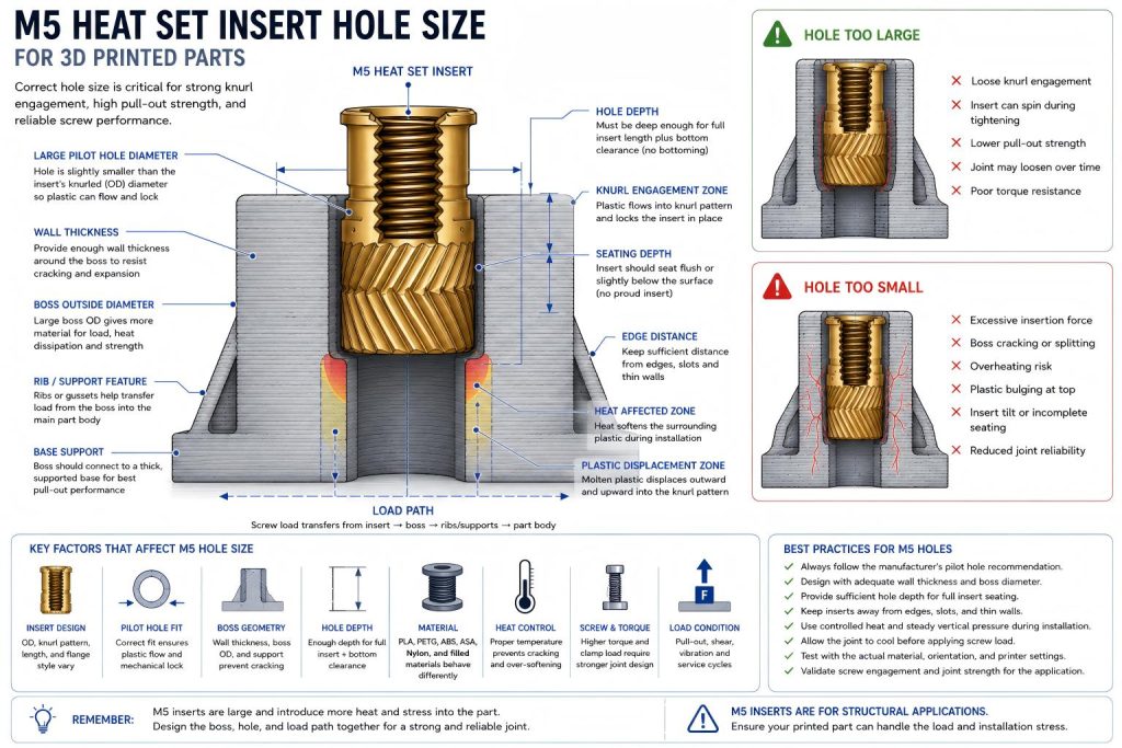
What Is the Recommended Hole Size for an M5 Heat Set Insert?
There is no single universal hole size for every M5 heat set insert. Insert outer diameter varies by manufacturer, insert length, knurl pattern, flange style, and body design.
The correct starting point is the manufacturer’s recommended pilot hole diameter for the exact M5 insert being used. In a 3D printed part, the pilot hole is usually designed slightly smaller than the insert’s outer knurled diameter so the heated insert can displace softened plastic and create mechanical engagement around the insert body.
For M5 inserts, the hole size must also account for the larger volume of displaced plastic and the greater heat mass of the brass insert. A hole that is too tight can crack or deform the boss. A hole that is too loose can reduce knurl engagement, torque resistance, and pull-out strength.
Why M5 Hole Size Needs Extra Design Margin
M5 heat set inserts are often used in large printed parts, structural brackets, machine fixtures, heavy covers, mounting blocks, equipment panels, and prototype assemblies that need stronger screws.
Compared with smaller insert sizes, M5 holes require more attention because:
- The insert displaces more plastic during installation.
- The boss must provide more surrounding wall thickness.
- The insert transfers more heat into the printed part.
- The hole must be deep enough for a longer insert body.
- The screw may apply higher tightening torque.
- The surrounding structure must support larger clamp loads.
- The insert is more likely to damage weak or undersupported bosses if the hole is wrong.
M5 should be treated as a structural fastening feature, not just a large hole in a printed part.
Key Variables That Affect M5 Heat Set Insert Hole Size
| Variable | Why It Matters |
|---|---|
| Insert outer diameter | The knurled body diameter defines the basic pilot hole range. |
| Insert length | M5 inserts are often longer and require enough hole depth and seating clearance. |
| Knurl geometry | Aggressive knurls need enough plastic flow but may increase insertion pressure. |
| Printed material | PLA, PETG, ABS, ASA, nylon, and filled materials soften and deform differently. |
| Boss outside diameter | A large insert needs enough surrounding plastic to resist cracking and expansion. |
| Wall thickness | Thin walls around an M5 insert are a major cracking and deformation risk. |
| Hole depth | Insufficient depth can cause bottoming, proud inserts, or reduced screw engagement. |
| Print tolerance | Printed holes may be undersized, oval, or affected by material shrinkage. |
| Insertion heat | M5 inserts store more heat and can over-soften the surrounding boss if uncontrolled. |
| Load condition | Higher screw loads require stronger hole support and better boss geometry. |
M5 Hole Size Is Part of the Structural Design
For M5 heat set inserts, the pilot hole should not be treated as an isolated dimension. It must work with the boss, screw, material, and load path.
Before finalizing an M5 pilot hole, review:
- Boss outside diameter
- Minimum wall thickness around the insert
- Hole depth and bottom clearance
- Insert seating depth
- Distance from the insert to edges, corners, slots, or thin walls
- Expected screw torque
- Screw engagement length
- Whether the joint will carry pull-out, shear, bending, vibration, or repeated assembly load
If the surrounding geometry cannot support the insert, increasing the insert size may create a larger failure rather than a stronger joint.
Hole Too Large: Common M5 Insert Problems
If the M5 pilot hole is too large, the insert may slide in easily but fail to create enough mechanical lock after cooling. Because M5 joints often carry higher loads, weak engagement can become a serious reliability problem.
Possible oversized-hole symptoms include:
- The insert enters with very little resistance.
- The insert can rotate during screw tightening.
- The screw tightens but the joint loses torque under load.
- The insert pulls out under axial load.
- The surrounding plastic does not fully engage the knurl pattern.
- The joint feels weak during repeated assembly.
An oversized M5 hole may reduce both torque resistance and pull-out strength, especially in structural parts.
Hole Too Small: Common M5 Insert Problems
If the M5 pilot hole is too small, the insert may require excessive heat or force to install. Because the insert is large, the resulting radial pressure and plastic displacement can damage the boss.
Possible undersized-hole symptoms include:
- The boss cracks during insertion.
- The insert stops before reaching full depth.
- Molten plastic bulges around the top of the hole.
- The insert tilts under installation pressure.
- The boss wall expands or deforms outward.
- The printed part surface warps near the insert.
- The insert overheats the surrounding plastic before seating properly.
This risk is especially important in PLA, thin bosses, edge locations, and large inserts installed without enough temperature control.
Material Considerations for M5 Heat Set Insert Holes
PLA
PLA can be stiff and dimensionally accurate, but it is less forgiving when the M5 pilot hole is too tight or the boss wall is thin. M5 inserts in PLA need conservative hole sizing, generous wall support, and controlled insertion pressure to reduce cracking risk.
PETG
PETG is more ductile than PLA, which can help during insertion, but it may deform under sustained clamp load or excessive heat. M5 holes in PETG should be tested for both installation fit and long-term joint behavior.
ABS and ASA
ABS and ASA may tolerate heat better than PLA and PETG, but M5 insert reliability still depends on printed hole quality, boss support, and layer adhesion. Large holes and thick bosses should still be validated with test parts.
Nylon and Filled Materials
Nylon and fiber-filled materials may provide toughness, but they vary strongly by formulation, moisture, fiber content, and print settings. M5 holes in these materials should be validated because heat transfer, surface texture, and plastic flow can differ from unfilled materials.
Blind Holes vs Through Holes for M5 Inserts
M5 heat set inserts are often used in thicker printed parts where blind holes are common. A blind hole must be deep enough for the full insert length, displaced plastic, and seating tolerance.
If a blind hole is too shallow, the insert may bottom out before seating properly. This can leave the insert proud of the surface, reduce screw engagement, or create internal pressure that cracks the boss.
Through holes can reduce bottoming risk, but they require controlled insertion so the insert does not sink below the intended seating plane.
Boss Geometry Around M5 Heat Set Insert Holes
The boss around an M5 insert must provide enough material to resist expansion, cracking, spin-out, and pull-out. A correct hole diameter cannot compensate for a weak boss.
Before using M5, check:
- Is the boss outside diameter large enough?
- Is the wall thickness sufficient around the hole?
- Is the insert too close to an edge or slot?
- Is the hole deep enough for the full insert length?
- Can the boss transfer load into the main printed part?
- Will the joint be tightened with high torque?
- Will the part be used in vibration or repeated assembly?
M5 inserts should not be forced into small bosses just because a larger screw seems stronger.
Heat Control During M5 Installation
M5 inserts store and transfer more heat than smaller inserts. This makes installation control especially important.
Too little heat can require excessive insertion force and crack the boss. Too much heat can over-soften the surrounding plastic, enlarge the hole, reduce knurl engagement, or deform the part surface.
Good M5 installation should focus on:
- Stable vertical alignment
- Gradual heat transfer
- Controlled insertion pressure
- Avoiding excessive dwell time
- Allowing the insert to seat without forcing it
- Letting the joint cool before loading the screw
When to Choose M5 Instead of M4
M5 inserts may be appropriate when the printed part has enough space for a large boss and the assembly needs stronger fastening than M4 can provide.
Common M5 use cases include:
- Large mounting blocks
- Heavy brackets
- Fixture bodies
- Machine panels
- Large service covers
- Structural prototype parts
- High-clamp-load assemblies
However, M5 should not be chosen only because it looks stronger. The printed part must have enough boss geometry, wall thickness, hole depth, and load path to support the larger insert.
Common Mistakes With M5 Heat Set Insert Hole Size
- Using a generic M5 hole size without checking the insert drawing.
- Assuming all M5 heat set inserts have the same outer diameter.
- Using M5 in a boss that is too small or too close to an edge.
- Making the pilot hole too tight in PLA.
- Ignoring the larger heat mass of the insert.
- Using a blind hole that is too shallow.
- Testing fit but not screw torque or load behavior.
- Overheating the printed boss during installation.
- Choosing M5 when M4 or multiple smaller fasteners would be safer.
Recommended Design Process for M5 Pilot Holes
- Start with the exact insert manufacturer’s pilot hole recommendation.
- Check the insert’s outer diameter, length, and knurl geometry.
- Confirm printed hole accuracy with the final material and printer settings.
- Design enough boss diameter, wall thickness, and depth around the hole.
- Check edge distance and load path into the main part.
- Print a test boss before committing to the final part.
- Install the insert with controlled heat and vertical pressure.
- Check for cracking, tilt, proud seating, plastic bulging, or overheating.
- Validate screw torque, pull-out behavior, and repeated assembly if relevant.
- Adjust boss geometry before relying only on hole diameter changes.
FAQ
What is the correct hole size for M5 heat set inserts?
✔ Answer:
For most M5 heat set inserts, the recommended hole size is typically 5.5 mm to 5.8 mm, depending on material type and insert geometry.
If the hole is too large, the insert may spin under load and lose structural integrity. If it is too small, it may crack PLA during installation. Incorrect sizing can significantly reduce load-bearing performance and long-term durability.
Related Engineering Guides
- Heat Set Insert Hole Size Guide
- M3 Heat Set Insert Hole Size for 3D Printed Parts
- M4 Heat Set Insert Hole Size for 3D Printed Parts
- M2 Heat Set Insert Hole Size for 3D Printed Parts
- How to Design Bosses for Heat Set Inserts
- Heat Set Insert Installation Temperature for 3D Printed Parts
- Torque Resistance of Heat Set Inserts in 3D Printed Parts
Related Engineering References
- M5 Heat Set Insert Dimensions Reference for 3D Printed Parts
- Heat Set Insert Hole Depth Chart for 3D Printed Parts
- Heat Set Insert Pilot Hole Tolerance Reference for 3D Printed Parts
- Heat Set Insert Minimum Wall Thickness Reference for 3D Printed Parts
- Heat Set Insert Seating Depth Reference for 3D Printed Parts
- Heat Set Insert Assembly Stack-Up Reference for 3D Printed Parts
Conclusion
M5 heat set insert hole size should be selected from the exact insert drawing and validated in the printed material, boss geometry, and installation method used in the final part. A correct M5 pilot hole is not only about diameter. It must also work with hole depth, wall thickness, heat control, screw torque, and the surrounding load path.
For large 3D printed parts, M5 inserts can create strong fastening structures only when the printed boss is designed to support the size, heat, and load of the insert.
Related Decision Resources
For insert selection, tool choice, and supplier comparison, use these decision-focused references after the engineering requirements are defined.