
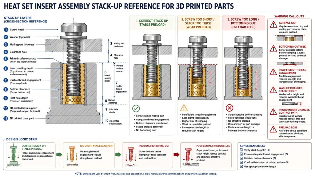
Heat Set Insert Assembly Stack-Up Reference for 3D Printed Parts explains how screw length, mating part thickness, insert seating depth, washer use, contact surface design, and thread engagement work together in heat set insert assemblies.
A heat set insert joint is not controlled by the insert alone. The final assembly depends on the full stack-up: the screw head, washer or mating part, clearance hole, printed surface, insert position, usable thread depth, and the bottom of the pilot hole. If these layers do not match, the joint may look assembled but still lose preload, bottom out, create surface gaps, or damage the printed boss.
This reference should be used as an engineering checklist for designing and checking heat set insert assemblies in 3D printed parts, especially lids, covers, brackets, fixtures, robotics panels, battery access plates, and serviceable parts.
What Assembly Stack-Up Means
Assembly stack-up describes the total path from the screw head to the threaded insert and into the printed plastic structure. It includes every layer the screw passes through before it creates clamping force.
In a simple heat set insert assembly, the stack-up may include:
- the screw head
- a washer, if used
- the mating part or cover
- the clearance hole through the mating part
- the printed surface around the insert
- the seated position of the heat set insert
- the usable internal thread length
- the screw engagement length
- the bottom of the pilot hole or internal clearance space
If any of these elements are mismatched, the assembly can fail even when the insert itself was installed correctly.
Why Stack-Up Matters for Heat Set Inserts
Heat set inserts are often used because they make printed parts more serviceable and durable. But serviceability depends on more than pull-out strength or torque resistance. The screw must clamp the correct surfaces together without bottoming out, tilting, lifting the insert, crushing the plastic, or losing preload over time.
A good stack-up allows the screw to generate clamping force through the intended contact surfaces. A bad stack-up may tighten against the wrong feature, such as the bottom of the hole, a proud insert top, a distorted plastic surface, or a screw that is too long for the available thread depth.
Stack-Up Elements in a Heat Set Insert Joint
| Stack-Up Element | What It Controls | Common Risk |
|---|---|---|
| Screw length | How far the screw reaches into the insert | Too short gives poor engagement; too long may bottom out. |
| Mating part thickness | How much material sits between screw head and printed base | Wrong thickness changes engagement and preload. |
| Washer or contact surface | How load spreads under the screw head | Small contact area can crush plastic or loosen over time. |
| Clearance hole | How freely the screw passes through the mating part | Tight clearance can cause misalignment or false torque readings. |
| Insert seating depth | Where the insert top sits relative to the printed surface | Proud or recessed inserts can change clamping behavior. |
| Usable thread depth | How much internal insert thread the screw can actually use | Blocked threads or over-insertion reduce engagement. |
| Bottom clearance | Space below the screw tip or insert | Insufficient clearance causes screw bottoming out. |
| Printed boss support | How the plastic carries load around the insert | Weak support causes cracking, spin, or preload loss. |
Assembly Stack-Up vs Screw Engagement Length
Screw engagement length is one part of the stack-up, but it is not the whole assembly. A screw can have enough thread engagement in theory and still fail if the mating part thickness, insert seating depth, washer thickness, or bottom clearance is wrong.
For example, if the insert sits too deep, the same screw may lose usable engagement. If a washer is added later, the screw may no longer reach enough threads. If the screw is too long, it may bottom out before clamping the mating part.
For thread engagement design, see Screw Engagement Length for Heat Set Inserts in 3D Printed Parts.
Assembly Stack-Up vs Insert Seating Depth
Insert seating depth affects how the mating part contacts the printed surface. If the insert sits proud above the surface, the mating part may rest on the insert instead of the surrounding plastic. If the insert sits too deep, the screw may need more length to reach the intended thread engagement.
A flush insert is often preferred for flat lids, panels, and covers. However, the correct seating condition depends on the assembly stack, screw length, and contact surface design.
For seating position design, see Heat Set Insert Seating Depth Reference for 3D Printed Parts.
Common Stack-Up Problems
Screw too short
A screw that is too short may only engage a few threads in the insert. The joint may feel tight at first, but it can loosen under vibration or repeated handling because the thread engagement is not deep enough.
Screw too long
A screw that is too long can bottom out inside the insert, at the bottom of the pilot hole, or against displaced plastic. When this happens, the screw may feel tight even though it is not clamping the mating part properly.
Mating part too thick
If the upper part is thicker than expected, the screw may not reach enough insert thread. This often happens when prototypes change cover thickness, washer use, or spacer height without updating screw length.
Washer added after design
A washer spreads load, but it also changes the stack height. If the screw length is not updated, thread engagement may become too short.
Insert sits proud
A proud insert can create a surface gap under the mating part. The screw may clamp against the insert top rather than pulling the mating surfaces together.
Insert sits too deep
A recessed or over-inserted insert can reduce usable thread access and require a longer screw. If the screw length is not adjusted, preload may be weak.
Clearance hole is too tight
A tight clearance hole in the mating part can prevent the screw from aligning naturally with the insert. This can cause cross-threading, false torque readings, or uneven clamping.
Bottoming Out Risk
Bottoming out is one of the most common stack-up mistakes. It happens when the screw reaches a hard stop before the mating part is fully clamped. This hard stop may be the bottom of the insert, the bottom of the printed pilot hole, trapped plastic, or another internal feature.
Bottoming out can be misleading because the screw may feel tight. In reality, the torque is being used to press the screw tip into an internal stop rather than to clamp the assembly.
Warning signs of bottoming out include:
- the screw tightens suddenly without pulling the parts together
- there is still a visible gap between mating surfaces
- the screw tip marks the bottom of the hole
- the insert lifts, spins, or deforms under tightening
- the joint loosens after handling or vibration
- different screws of the same nominal size behave inconsistently
For hole depth planning, see Heat Set Insert Hole Depth Chart for 3D Printed Parts.
Surface Contact and Clamping Path
A reliable insert joint needs a clear clamping path. The screw head should press the mating part against the intended printed surface. The insert should provide threaded resistance, not act as a spacer that holds the mating part away from the base.
If the contact surface is too small, uneven, warped, or interrupted by a proud insert, the assembly may lose preload. If the printed plastic creeps under the screw head or washer, the joint may become loose even though the insert remains in place.
For torque behavior, see Heat Set Insert Torque Range Reference for 3D Printed Parts.
Washer Use in Printed Insert Assemblies
Washers can help spread load under the screw head and reduce local crushing of printed plastic. They are especially useful when the mating part is plastic, thin, soft, slotted, or repeatedly removed.
However, washers also increase stack height. If a washer is added after the screw length has already been selected, the screw may no longer engage enough insert threads. A washer should be treated as part of the stack-up, not as a harmless add-on.
| Washer Condition | Potential Benefit | Stack-Up Risk |
|---|---|---|
| No washer | Simple assembly and shorter stack height | Small screw head may crush plastic or create preload loss. |
| Flat washer | Spreads load over a wider area | Reduces available screw engagement if screw length is unchanged. |
| Large washer | Improves load distribution on soft or slotted parts | May interfere with nearby geometry or create uneven contact. |
| Spring washer | May help in some vibration conditions | Can damage plastic or create inconsistent preload if misused. |
Stack-Up and Repeated Assembly
Repeated assembly makes stack-up errors more visible. A joint may survive one installation, but repeated screw removal can expose weak thread engagement, poor contact surfaces, insert movement, or plastic creep.
Service panels, electronics covers, robot joint panels, battery access plates, and modular prototypes should be checked after multiple open-close cycles. The screw should still tighten smoothly, the insert should not rotate, and the mating surfaces should still sit flat.
For repeated-use behavior, see Heat Set Inserts for Repeated Assembly in 3D Printed Parts.
Material Behavior in Stack-Up Design
Different printed materials respond differently to clamping force. PLA may hold shape well at first but crack or soften near heat. PETG may tolerate impact but slowly lose preload. ABS and ASA can handle more temperature, but print quality and layer adhesion still matter. Nylon may absorb load but relax under sustained clamping.
| Material | Stack-Up Concern | Design Note |
|---|---|---|
| PLA | Brittle cracking or heat-related deformation | Avoid over-tightening and use clear support geometry. |
| PETG | Creep and preload loss | Use washers, broad contact surfaces, and cycle testing. |
| ABS | Layer splitting and dimensional variation | Check flatness, seating, and screw engagement after cooling. |
| ASA | Similar to ABS with better outdoor stability | Still needs stack validation under repeated assembly. |
| Nylon | Flexibility and preload relaxation | Use generous contact surfaces and check long-term clamp stability. |
| Fiber-filled materials | High stiffness but local brittleness | Avoid point loading and sharp stress paths. |
For material comparison, see PLA vs PETG vs ABS for Threaded Inserts.
Assembly Stack-Up Checklist
Before choosing a final screw length or publishing a printed part design, check the full assembly stack instead of checking the insert alone.
- Measure the mating part thickness.
- Include washer thickness if washers are used.
- Confirm the insert seating depth after installation.
- Confirm usable thread access inside the insert.
- Check that the screw does not bottom out.
- Check that the screw has enough engagement length.
- Confirm that the mating part sits flat against the printed surface.
- Confirm that the screw clearance hole does not force misalignment.
- Check that the printed boss has enough wall support.
- Retest after changing screw length, washer use, material, or insert size.
Test Coupon Method
The best way to validate assembly stack-up is to test the real screw, real insert, real mating thickness, and real printed geometry together. A single insert installed in a block does not reveal stack-up problems.
A useful test coupon should include:
- the same insert size and insert length
- the same seating depth target
- the same pilot hole and hole depth
- the same printed boss or wall support geometry
- the same mating part thickness
- the same washer, if used
- the same screw length and screw head type
- the same screw clearance hole condition
- the same tightening torque range
- the same repeated assembly cycle requirement
After assembly, check clamping, surface gap, bottoming out, screw engagement, insert spin, preload retention, and repeated screw removal behavior.
Common Mistakes
Choosing screw length before checking the full stack
Screw length should be selected after mating thickness, washer use, insert seating depth, and thread access are known.
Assuming the insert is the only important part
The insert provides the thread, but the stack-up determines whether the screw actually clamps the assembly correctly.
Ignoring washer thickness
A washer can improve load distribution but reduce thread engagement if screw length is not adjusted.
Confusing screw tightness with clamping force
A screw can feel tight because it bottomed out, not because it clamped the mating part properly.
Changing cover thickness without changing screw length
Prototype covers often change thickness during design. If screw length is not updated, engagement or bottom clearance may become unsafe.
FAQ
What is assembly stack-up for heat set inserts?
Assembly stack-up is the full layered relationship between the screw head, washer, mating part, clearance hole, printed surface, insert seating depth, thread engagement, and bottom clearance.
Why can a heat set insert joint feel tight but still be loose?
The screw may be bottoming out before clamping the mating part. In that case, torque creates a tight feeling, but the joint does not have proper preload.
Does washer thickness affect screw engagement?
Yes. A washer increases the stack height. If screw length is not adjusted, the screw may engage fewer insert threads.
How do I avoid screw bottoming out in a heat set insert assembly?
Check screw length, mating part thickness, washer thickness, insert seating depth, usable thread depth, and hole bottom clearance together before final assembly.
Is screw engagement length enough to design the joint?
No. Screw engagement is important, but the full stack-up must also account for seating depth, contact surface, washer use, clearance holes, and bottoming out risk.
Related Guides
- Screw Engagement Length for Heat Set Inserts in 3D Printed Parts
- Heat Set Insert Seating Depth Reference for 3D Printed Parts
- Heat Set Insert Torque Range Reference for 3D Printed Parts
- Heat Set Insert Hole Depth Chart for 3D Printed Parts
- Heat Set Insert Minimum Wall Thickness Reference for 3D Printed Parts
- Heat Set Inserts for Repeated Assembly in 3D Printed Parts
- Why Does Screw Preload Drop in 3D Printed Insert Joints?
- Why Do Threaded Inserts Loosen After Repeated Screw Removal?