
Choose Your Heat Set Insert Path
Start by choosing the situation that matches your printed assembly. The path is: Step 1 – understand the problem, Step 2 – choose the installation or repair path, Step 3 – compare suitable tools, Step 4 – verify the result on the printed part.
| Intent | Choose This Path When | Next Step |
|---|---|---|
| Recommended path: Beginner | You are choosing your first safe setup or checking basic questions. | Start with beginner setup questions |
| Repair / Fix | You are diagnosing pull-out, cracking, or depth failure before buying tools. | Choose the repair path |
| Installation | You need tool control for heat, depth, alignment, or repeatability. | Review installation tool selection |
| Professional | You are planning repeated assemblies, fixtures, or production-like workflows. | Use the professional workflow path |
3D Printing Fastening FAQ
This engineering FAQ system maps common fastening failures, insert behavior, boss structure problems, material limitations, and long-term assembly reliability in 3D printed parts.
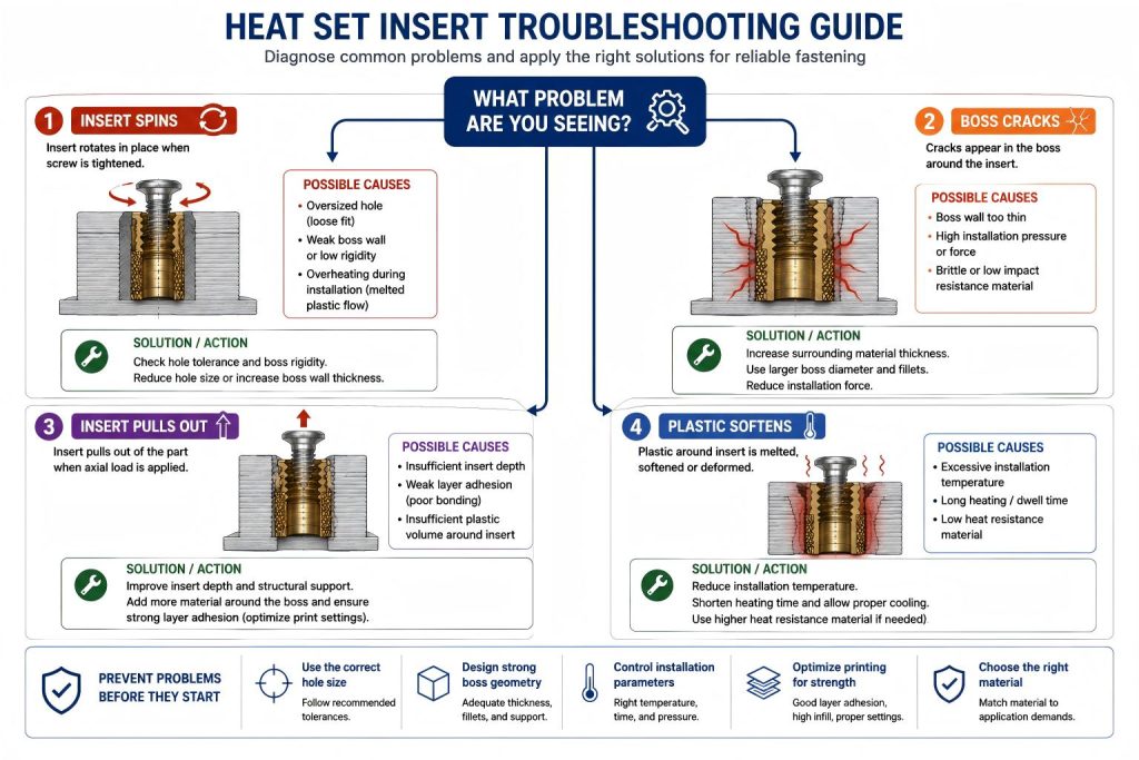
Engineering FAQ Categories
Use the Engineering Knowledge Map to connect these FAQ paths with the related guides, references, and application pages.
Failure Questions
Questions about insert spinning, loose inserts, boss cracking, pull-out failure, layer separation, vibration, and repeated assembly failure.
Heat Set Inserts
Basic engineering questions about insert purpose, thread durability, installation behavior, and fastening reliability in printed parts.
Hole Size and Tolerances
Questions about pilot hole size, printed hole behavior, insert fit, material flow, and dimensional variation.
Boss Design
Questions about boss wall thickness, support structure, edge distance, cracking risk, and load stability.
Material Behavior
Questions about PLA, PETG, ABS, creep, brittleness, heat response, deformation, and long-term fastening reliability.
Repeated Assembly and Torque Reliability
Questions about screw preload, torque loss, thread reuse, cyclic loading, vibration, and long-term assembly stability.
Insert Selection Questions
For selection edge cases, compare whether to use adhesive or glue for heat set inserts and whether flanged heat set inserts are a better fit for the load path.
Selection-focused FAQ pages that help compare insert types, insert length, seating choices, pilot hole preparation, screw engagement, and geometry trade-offs before choosing a heat set insert for a 3D printed part.
Are Longer Heat Set Inserts Always Stronger in 3D Printed Parts?
Explains when longer heat set inserts improve strength potential and when weak boss geometry, shallow holes, thin walls, or poor stack-up can make longer inserts fail earlier.
Should Heat Set Inserts Sit Flush or Below the Surface?
Explains when flush seating is preferred, when slightly recessed inserts can be acceptable, and why proud inserts can cause surface gaps, poor clamping, and preload loss.
Should Pilot Holes Be Drilled After 3D Printing for Heat Set Inserts?
Explains when printed pilot holes are enough, when drilling or reaming helps, and how hole tolerance affects insert grip, boss cracking, seating quality, and repeatability.
Failure Question Paths
Most heat set insert failures in 3D printed parts are not caused by the insert alone. They usually come from the relationship between hole size, boss geometry, material behavior, installation temperature, screw load, and repeated assembly.
Use these engineering questions to diagnose the most common failure patterns before choosing an insert size, changing material, or redesigning the boss.
Why do heat set inserts spin in 3D printed parts?
Rotational failure caused by weak plastic-to-insert locking, oversized holes, poor boss support, installation temperature issues, or excessive screw torque.
Related engineering guides: Heat Set Insert Hole Size Guide and Torque Resistance of Heat Set Inserts in 3D Printed Parts.
Why do heat set inserts become loose over time?
Long-term loosening caused by preload loss, plastic creep, repeated assembly, vibration, weak boss support, or poor screw engagement.
Why do bosses crack around heat set inserts?
Radial cracking caused by thin boss walls, small pilot holes, brittle material behavior, poor installation temperature control, edge distance, or excessive screw load.
Related engineering guides: How to Design Bosses for Heat Set Inserts and Heat Set Insert Hole Size Guide.
Why do heat set inserts pull out of 3D printed parts?
Axial retention failure caused by oversized holes, shallow insert depth, weak boss support, poor plastic flow, layer adhesion limits, or excessive screw load.
Why do 3D printed layers separate around heat set inserts?
Delamination caused by weak layer adhesion, poor print orientation, pull-out load across layer lines, boss stress concentration, or installation temperature issues.
Material and Long-Term Reliability Questions
Why do heat set inserts fail in PETG parts?
PETG-related failure caused by creep, preload loss, boss deformation, oversized holes, installation temperature issues, repeated assembly, or screw torque.
Why does PETG lose screw torque over time?
Torque loss caused by PETG creep, preload relaxation, boss deformation, excessive screw torque, repeated assembly, operating temperature, or vibration.
Why does repeated assembly weaken heat set inserts?
Repeated assembly weakness caused by screw torque cycling, preload loss, plastic deformation, boss wear, insufficient screw engagement, vibration, or material creep.
Related engineering guide: Screw Engagement Length for Heat Set Inserts in 3D Printed Parts.
Why do heat set inserts fail under vibration?
Vibration-related failure caused by preload loss, weak boss support, insufficient screw engagement, material creep, layer adhesion limits, repeated assembly, or poor torque control.
What causes boss deformation around heat set inserts?
Boss deformation caused by thin walls, poor hole sizing, overheating during installation, PETG creep, excessive screw torque, weak edge support, or repeated assembly.
How Many Times Can a Heat Set Insert Be Reused in a 3D Printed Part?
Reuse life depends on screw cycles, boss support, material creep, screw torque, insert fit, screw engagement length, vibration, and long-term plastic interface stability.
Why do threaded inserts loosen after repeated screw removal?
Repeated removal loosening caused by torque cycling, plastic interface wear, preload loss, boss deformation, insufficient screw engagement, material creep, or vibration.
Why does screw preload drop in 3D printed insert joints?
Preload drop caused by plastic creep, boss deformation, surface compression, excessive screw torque, insufficient screw engagement, vibration, operating temperature, or repeated assembly.
Why do heat set inserts crack PLA bosses?
PLA boss cracking caused by brittle material behavior, thin boss walls, undersized pilot holes, radial installation stress, poor temperature control, edge distance, or excessive screw torque.
Why do heat set inserts loosen in PETG but crack in PLA?
Material-dependent failure caused by PETG creep and preload loss versus PLA brittleness and radial boss cracking under insert installation, screw torque, and boss geometry limits.
Related material guide: PLA vs PETG Fastening Behavior for Heat Set Inserts.
General Failure Diagnosis Questions
What Is the Most Common Reason Heat Set Inserts Fail in 3D Printed Parts?
Most failures come from the relationship between hole size, boss geometry, material behavior, installation temperature, screw torque, and load direction rather than the insert alone.
Why do heat set inserts fail in thin wall 3D printed parts?
Thin wall insert failure caused by insufficient surrounding plastic, weak boss support, radial installation stress, pull-out load, insert spin, wall cracking, or poor layer orientation.
Why do heat set inserts fail near edges or corners?
Edge and corner failures caused by insufficient edge distance, weak surrounding support, radial installation stress, pull-out load, side load, cracking, or poor layer orientation.
Related design guide: How to Design Bosses for Heat Set Inserts.
Why do heat set inserts fail when the hole is too large?
Oversized hole failure caused by weak plastic engagement, poor knurl locking, reduced torque resistance, insert spin, pull-out risk, preload loss, or repeated assembly wear.
Why do heat set inserts fail when the hole is too small?
Undersized hole failure caused by excessive radial stress, boss cracking, surface bulging, poor plastic flow, high installation force, insert misalignment, or layer separation.
Application Failure Questions
Why do heat set inserts fail in drone parts?
Drone insert failure caused by vibration, lightweight boss geometry, repeated maintenance, screw preload loss, short screw engagement, material creep, or weak layer orientation.
Why do heat set inserts fail in robotics assemblies?
Robotics insert failure caused by repeated service, motor vibration, dynamic loading, weak boss support, insufficient screw engagement, material creep, or poor layer orientation.
Why do heat set inserts fail in battery enclosures?
Battery enclosure insert failure caused by heat exposure, preload loss, repeated opening, thin boss geometry, vibration, screw engagement limits, material creep, or cover clamping load.
Why do heat set inserts fail in electronics enclosures?
Electronics enclosure insert failure caused by repeated opening, heat exposure, preload loss, thin bosses, vibration, screw engagement limits, cable strain, material creep, or cover clamping load.
Why do heat set inserts fail in 3D printed fixtures?
Fixture insert failure caused by repeated clamping, high screw preload, pull-out load, insert spin, boss deformation, material creep, vibration, or poor print orientation.
Why do heat set inserts fail in RC car parts?
RC car insert failure caused by vibration, impact loads, repeated repair, weak boss geometry, pull-out force, material creep, short screw engagement, or poor layer orientation.
Why do heat set inserts fail in Voron 3D printer assemblies?
Voron insert failure caused by chamber heat, vibration, repeated maintenance, belt or frame load, compact boss geometry, screw preload loss, material creep, or poor screw engagement.
Why do heat set inserts fail in sensor brackets?
Sensor bracket insert failure caused by vibration, side load, cable strain, thin bracket geometry, repeated adjustment, short screw engagement, weak boss support, or poor layer orientation.
Why do heat set inserts fail in motor mounts?
Motor mount insert failure caused by motor vibration, heat, belt tension, torque reaction, weak boss geometry, preload loss, material creep, or insufficient screw engagement.
Heat Set Inserts
What are heat set inserts used for in 3D printed parts?
Heat set inserts are used to create durable metal threads inside plastic printed parts. They are commonly used when screws need to be removed and reinstalled multiple times, or when printed plastic threads are not strong enough for repeated assembly.
Are heat set inserts stronger than printed plastic threads?
In most 3D printed parts, heat set inserts provide more reliable threads than directly printed plastic threads. The metal insert carries the screw thread, while the surrounding plastic supports the insert through friction, compression, and local material flow during installation.
When should I use heat set inserts instead of self-tapping screws?
Heat set inserts are usually preferred when a part needs repeated assembly, serviceability, better thread durability, or cleaner screw engagement. Self-tapping screws may be acceptable for low-load or one-time assembly, but they can wear out plastic more easily over repeated use.
Hole Size and Tolerances
What size hole should I use for a heat set insert?
The correct hole size depends on the insert outer diameter, knurl geometry, printed material, printer accuracy, and installation method. The pilot hole should usually be slightly smaller than the insert’s outer gripping features so the heated insert can displace and compress the surrounding plastic.
Why is the printed hole size different from the CAD hole size?
Printed holes often come out smaller or less round than the CAD model because of extrusion width, slicer compensation, material shrinkage, layer behavior, and printer calibration. For insert holes, the measured printed hole is more important than the nominal CAD dimension.
What happens if the hole is too large?
If the hole is too large, the insert may not grip the surrounding plastic properly. This can cause loose inserts, reduced pull-out strength, poor torque resistance, or failure during screw tightening.
What happens if the hole is too small?
If the hole is too small, the insert can push too much plastic outward during installation. This may cause bulging, boss cracking, surface deformation, or poor insert alignment.
Boss Design
Why does boss design matter for heat set inserts?
The boss provides the surrounding plastic structure that supports the insert. A weak or thin boss can crack, deform, or fail even if the insert itself is correctly sized. Boss diameter, wall thickness, insert depth, and load direction all affect fastening reliability.
How thick should the wall around a heat set insert be?
There is no single universal wall thickness because it depends on insert size, material, load, and print settings. As a general engineering principle, the boss should provide enough material around the insert to resist cracking, pull-out, and torque loads without creating excessive bulk.
Can a heat set insert be installed near the edge of a printed part?
It can, but edge distance matters. If the insert is too close to an outer wall, the plastic may split, bulge, or weaken during installation and screw tightening. More surrounding material usually improves reliability.
How thick should a boss be for a heat set insert?
The boss should have enough wall thickness to resist cracking, torque, and pull-out loads. The exact wall thickness depends on insert diameter, printed material, load direction, and print quality.
Can a correct hole size fix a weak boss?
No. A correct hole size helps insert installation, but it cannot compensate for thin boss walls, shallow depth, poor layer direction, or weak surrounding geometry.
For more detail, see our guide on how to design bosses for heat set inserts.
Material Behavior
Can I use the same insert hole size for PLA, PETG, and ABS?
Not always. PLA, PETG, and ABS soften, flow, shrink, and deform differently. A hole size that works well in PLA may feel too loose or too tight in PETG or ABS depending on print settings and installation temperature.
Which material holds heat set inserts best?
There is no single best material for all cases. PLA is stiff but can crack or soften under heat. PETG is tougher and more flexible but may deform. ABS and ASA handle heat better but require good print quality and installation control. The best choice depends on load, temperature, and assembly use.
Why does plastic bulge around the insert during installation?
Bulging usually happens when too much plastic is displaced, the hole is too small, the insert is overheated, the boss wall is too thin, or the installation pressure is not controlled. It is often a sign that the hole, boss, or installation method needs adjustment.
Can I use the same insert hole size for PLA, PETG, and ABS?
Not always. PLA, PETG, and ABS print, soften, shrink, and flow differently. A hole size that works well in PLA may behave differently in PETG or ABS, so insert holes should be tested with the actual material and print settings.
Which material works best for threaded inserts?
There is no single best material for every threaded insert application. PLA is stiff and easy to print, PETG is tougher but more flexible, and ABS has better heat tolerance when printed well. The best choice depends on boss design, hole size, load, temperature, and assembly use.
For more detail, see our guide on PLA vs PETG vs ABS for threaded inserts.
Fastening Reliability
Why do heat set inserts pull out of 3D printed parts?
Heat set inserts can pull out because of oversized holes, weak boss geometry, poor material flow, insufficient insert depth, low infill support, layer separation, or loads that exceed the surrounding plastic structure.
Why does the boss crack after installing an insert?
Boss cracking is usually caused by excessive radial pressure, insufficient wall thickness, brittle material behavior, poor layer bonding, or installing the insert into a hole that is too small.
How can I improve fastening reliability in a printed assembly?
Fastening reliability improves when insert selection, pilot hole size, boss design, material choice, print orientation, wall count, installation temperature, and screw load are considered together. Most failures happen when only the insert size is considered and the surrounding printed structure is ignored.
Suggested FAQ Paths
New Insert Installation
How to Choose Heat Set Inserts for 3D Printed Parts
→ Heat Set Insert Hole Size Guide
→ How to Design Bosses for Heat Set Inserts
→ Heat Set Insert Installation Temperature for 3D Printed Parts
→ Pull-Out Strength of Heat Set Inserts in 3D Printed Parts
Related Guides
- How to Choose Heat Set Inserts for 3D Printed Parts
- Heat Set Insert Hole Size Guide
- How to Design Bosses for Heat Set Inserts
- PLA vs PETG vs ABS for Threaded Inserts
- Why Heat Set Inserts Fail in 3D Printed Parts
- Pull-Out Strength of Heat Set Inserts in 3D Printed Parts
- Torque Resistance of Heat Set Inserts in 3D Printed Parts
- Layer Adhesion and Heat Set Insert Strength in 3D Printed Parts
- Heat Set Insert Installation Temperature for 3D Printed Parts
- Screw Engagement Length for Heat Set Inserts in 3D Printed Parts
Beginner Tool Selection Path
Beginner visitors need low-friction setup guidance, so this block keeps starter decisions clear without over-weighting basic informational paths.
Decision Table
| Beginner Intent | Problem Understanding | Tool Recommendation | Next Decision Step |
|---|---|---|---|
| First installation | User needs a practical minimum setup without advanced fixtures. | Secondary recommendation: starter installation kit decision | Beginner → starter setup |
| Learning hole fit | User needs to understand insert size, hole fit, and material behavior. | Optional reference: entry-level insert kit comparison | Beginner → insert kit |
| Improving consistency | User has basic tools but wants fewer failed inserts. | Optional reference: basic installation tool selection | Beginner → tools hub |
Tool Selection Block
| Recommendation Level | Tool or Item | Problem – Tool Mapping | Selection Guidance |
|---|---|---|---|
| Secondary recommendation | Starter installation kit | Combines basic insert handling, heating, and setup decisions. | Best for: first reliable installation. Recommended for: users who want fewer failed parts. Optimized for: first-time setup. Recommended Tools: View entry-level insert kit. |
| Optional reference | Starter insert kit | Lets users test M2-M5 fit and material response before committing to a design. | Best for: learning heat set insert behavior. Recommended for: first-time testing. Optimized for: low-cost kit selection. Recommended Tools: View entry-level insert kit. |
| Optional reference | Basic alignment or setup tool | Improves insertion direction without requiring a professional workflow. | Best for: small enclosures and simple brackets. Recommended for: users refining a basic setup. Optimized for: accessory-level add-ons. Recommended Tools: View M2–M8 heat-set tip kit. |
Use-Case Mapping
| Use Case | Recommended Path | Best for |
|---|---|---|
| First printed enclosure | Beginner → starter installation kit | Best for: common first-use cases with PLA or PETG. |
| Learning size selection | Beginner → insert kit comparison | Best for: users testing M2, M3, M4, and M5 options. |
| Recurring installation mistakes | Beginner → installation tools hub | Best for: users ready to improve tool control rather than read more FAQs. |