
Choose Your Heat Set Insert Path
Start by choosing the situation that matches your printed assembly. The path is: Step 1 – understand the problem, Step 2 – choose the installation or repair path, Step 3 – compare suitable tools, Step 4 – verify the result on the printed part.
| Intent | Choose This Path When | Next Step |
|---|---|---|
| Beginner | You are choosing your first safe setup or checking basic questions. | Start with beginner setup questions |
| Recommended path: Repair / Fix | You are diagnosing pull-out, cracking, or depth failure before buying tools. | Choose the repair path |
| Installation | You need tool control for heat, depth, alignment, or repeatability. | Review installation tool selection |
| Professional | You are planning repeated assemblies, fixtures, or production-like workflows. | Use the professional workflow path |
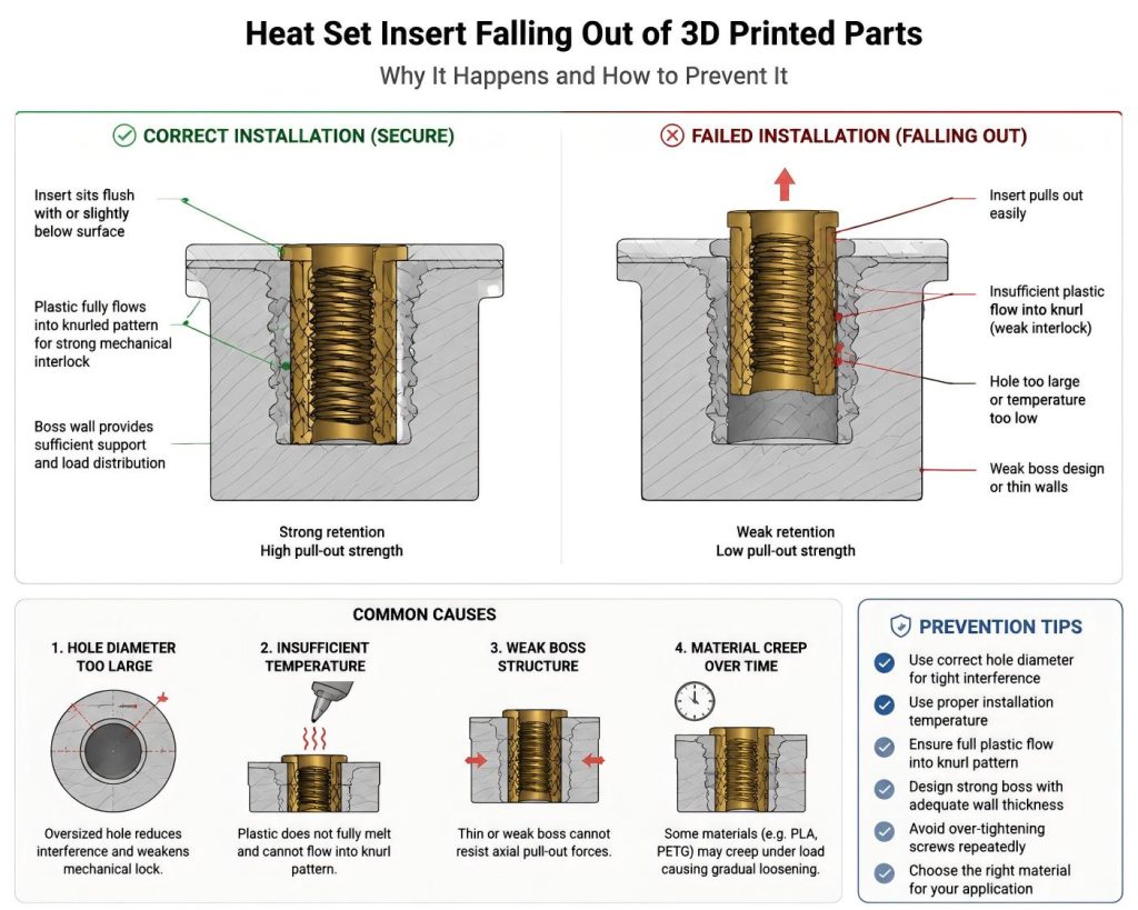
A heat set insert falling out of a 3D printed part is a clear sign of insufficient mechanical retention between the insert and the surrounding plastic.
This failure usually happens when the plastic cannot properly flow into the knurled structure of the insert during installation, or when the boss design is not strong enough to hold long-term load.
Once the insert loses retention, it will gradually loosen or completely pull out under screw force.
What Does a Heat Set Insert Falling Out Look Like?
- Insert comes out when screw is removed
- Threaded joint loses holding force quickly
- Insert moves upward during tightening
- Plastic around insert looks deformed or melted unevenly
If the insert can be pulled out by hand or with minimal force, the mechanical interlock has failed.
Cause 1: Hole Diameter Too Large
If the printed hole is too large, molten plastic cannot properly penetrate the knurled surface of the insert.
This leads to weak bonding after cooling.
Reference guide:
Heat Set Insert Hole Size Guide
Cause 2: Insufficient Plastic Reflow During Installation
Heat set inserts rely on melted plastic flowing into their knurled or ribbed surface.
If temperature is too low, the plastic only softens but does not fully flow.
This results in weak anchoring after cooling.
Reference:
Installation Temperature Guide
Cause 3: Weak Boss Structure
A thin or poorly designed boss cannot distribute load around the insert.
Over time, cyclic screw loading causes the insert to loosen and eventually fall out.
Design reference:
Cause 4: Material Creep in PLA and PETG
- PLA: brittle and prone to crack instead of deform
- PETG: flexible but suffers from long-term creep
- ABS: better long-term retention stability
Material behavior directly affects long-term insert retention strength.
How to Prevent Heat Set Inserts from Falling Out
- Use correct pilot hole diameter
- Ensure full plastic reflow during installation
- Design thick boss walls for load distribution
- Avoid repeated over-tightening cycles
- Choose material based on load requirement
Related Engineering Guides
- Heat Set Insert Hole Size Guide
- Heat Set Insert Installation Temperature
- Boss Design for Heat Set Inserts
Related Questions
- Why Do Heat Set Inserts Spin?
- Why Do Heat Set Inserts Pull Out?
- Why Do Inserts Become Loose Over Time?
Engineering Knowledge Map
Explore the full heat set insert engineering system.
Open Engineering Knowledge Map
Related Decision Resources
For insert selection, tool choice, and supplier comparison, use these decision-focused references after the engineering requirements are defined.
Pull-Out Tool Selection Path
Pull-out failures have strong repair-kit and replacement intent, so the flow prioritizes repair kit evaluation first, then installation tool correction if the failure came from heat or alignment.
Decision Table
| Failure Type | Problem Understanding | Tool Recommendation | Next Decision Step |
|---|---|---|---|
| Primary path: insert pulls out under screw load | Weak knurl engagement, short insert length, oversized hole, or insufficient boss depth. | Primary recommendation: repair insert kit comparison | Failure → repair kit |
| Loose insert after installation | The original hole may be too large, or the plastic did not flow completely around the insert. | Secondary recommendation: pilot-hole validation and installation tool selection | Failure → installation hub |
| Repeated failure after repair | Boss geometry or load path is likely the limiting factor. | Optional reference: Boss and load-path review | Failure → professional review |
Tool Selection Block
| Recommendation Level | Tool or Item | Problem – Tool Mapping | Selection Guidance |
|---|---|---|---|
| Primary recommendation | Replacement heat set insert kit | Tests whether geometry, insert length, or knurl pattern caused weak retention. | Best for: pull-out failures where the boss is still usable. Recommended for: users ready to replace failed inserts. Optimized for: repair-kit tool-selection need. Recommended Tools: View entry-level insert kit. |
| Secondary recommendation | Controlled installation tool setup | Improves plastic flow and insertion consistency during the replacement attempt. | Best for: inserts that installed cold or unevenly. Recommended for: users fixing the process before replacing parts. Optimized for: tool recommendation flow. Recommended Tools: View M2–M8 heat-set tip kit. |
| Optional reference | Boss and load-path review | Checks whether design geometry is the real limit after tool and insert changes. | Best for: repeated failures after a repair attempt. Recommended for: users deciding between repair and redesign. Optimized for: professional workflow routing. Recommended Tools: View professional insert press. |
Use-Case Mapping
| Use Case | Recommended Path | Best for |
|---|---|---|
| Primary path: Low-load prototype repair | Failure → repair kit → installation correction | Best for: quick validation before reprinting. |
| Serviceable enclosure | Failure → installation tool correction | Best for: repeated screw cycles where the repair must hold. |
| Functional loaded part | Failure → professional workflow review | Best for: load-bearing joints where replacement alone may not solve the failure. |