
Choose Your Heat Set Insert Path
Start by choosing the situation that matches your printed assembly. The path is: Step 1 – understand the problem, Step 2 – choose the installation or repair path, Step 3 – compare suitable tools, Step 4 – verify the result on the printed part.
| Intent | Choose This Path When | Next Step |
|---|---|---|
| Beginner | You are choosing your first safe setup or checking basic questions. | Start with beginner setup questions |
| Recommended path: Repair / Fix | You are diagnosing pull-out, cracking, or depth failure before buying tools. | Choose the repair path |
| Installation | You need tool control for heat, depth, alignment, or repeatability. | Review installation tool selection |
| Professional | You are planning repeated assemblies, fixtures, or production-like workflows. | Use the professional workflow path |
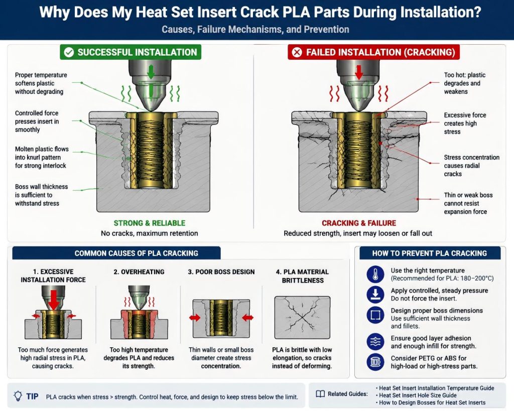
A heat set insert cracking PLA during installation is a common failure mode in 3D printed parts, especially when the boss design or installation parameters are not properly controlled.
This failure happens when stress concentration exceeds the tensile strength of PLA, causing radial cracks around the insert.
Once cracking starts, the structural integrity of the joint is permanently compromised.
What Does PLA Cracking Around Heat Set Inserts Look Like?
- Radial cracks spreading from insert hole
- Bursting or splitting of boss wall
- Insert becomes loose immediately after installation
- Visible whitening stress marks in PLA
PLA is brittle, so once stress exceeds its limit, it fails suddenly instead of deforming.
Cause 1: Excessive Installation Force
If too much downward force is applied during insertion, the PLA boss cannot distribute the load evenly.
This leads to immediate cracking around the insert.
Cause 2: Overheating During Installation
Excessive heat can weaken PLA locally, creating uneven soft zones.
When force is applied on a weakened structure, cracking becomes more likely.
Reference:
Heat Set Insert Installation Temperature Guide
Cause 3: Poor Boss Design
Thin walls or insufficient boss diameter create high stress concentration around the insert.
This is one of the most common root causes of PLA cracking failures.
Design reference:
Cause 4: PLA Material Brittleness
PLA has low elongation at break, which means it cannot absorb stress through deformation.
- PLA → brittle failure (cracking)
- PETG → ductile deformation
- ABS → higher impact resistance
How to Prevent PLA Cracking Around Heat Set Inserts
- Use controlled insertion force (do not press aggressively)
- Maintain correct installation temperature
- Increase boss wall thickness
- Avoid sharp internal stress corners
- Consider PETG or ABS for high-load applications
Related Engineering Guides
- Heat Set Insert Hole Size Guide
- Heat Set Insert Installation Temperature
- Boss Design for Heat Set Inserts
Related Questions
- Why Do Inserts Crack PLA Bosses?
- Why Do Inserts Fail When Hole Is Too Small?
- Why Do Inserts Fail Near Edges?
Engineering Knowledge Map
Explore the full heat set insert failure system and design knowledge base.
Open Engineering Knowledge Map
Related Decision Resources
For insert selection, tool choice, and supplier comparison, use these decision-focused references after the engineering requirements are defined.
PLA Cracking Tool Selection Path
PLA cracking usually creates immediate tool-correction intent, so controlled heat and alignment tools are prioritized before secondary process notes.
Decision Table
| Failure Type | Problem Understanding | Tool Recommendation | Next Decision Step |
|---|---|---|---|
| Primary path: boss cracks during insertion | Overheating, undersized hole, off-axis force, or brittle thin-wall PLA structure. | Primary recommendation: controlled installation tool selection | Failure → installation hub |
| Repeated cracking across several bosses | The installation process is not repeatable enough for the part geometry. | Secondary recommendation: alignment or press method comparison | Failure → alignment tools |
| Repeated failure after repair | Boss geometry or load path is likely the limiting factor. | Optional reference: Boss geometry review | Failure → professional review |
Tool Selection Block
| Recommendation Level | Tool or Item | Problem – Tool Mapping | Selection Guidance |
|---|---|---|---|
| Primary recommendation | Temperature-controlled installation setup | Controls heat input and insertion speed so PLA softens without splitting the boss. | Best for: PLA bosses cracking during insertion. Recommended for: users who need controlled heat before retrying. Optimized for: controlled-tool conversion. Recommended Tools: View M2–M8 heat-set tip kit. |
| Secondary recommendation | Alignment jig or press method | Reduces side load that can split small PLA bosses. | Best for: repeated PLA inserts and small boss diameters. Recommended for: users seeing cracks on multiple holes. Optimized for: alignment accessory selection. Recommended Tools: View heat-set insert tip. |
| Optional reference | Boss geometry review | Checks whether design geometry is the real limit after tool and insert changes. | Best for: repeated failures after a repair attempt. Recommended for: users deciding between repair and redesign. Optimized for: professional workflow routing. Recommended Tools: View entry-level insert kit. |
Use-Case Mapping
| Use Case | Recommended Path | Best for |
|---|---|---|
| Primary path: Small PLA boss repair decision | Failure → controlled tool setup → boss geometry check | Best for: preventing a second cracked part after the first failure. |
| Serviceable enclosure | Failure → installation tool correction | Best for: repeated screw cycles where the repair must hold. |
| Functional loaded part | Failure → professional workflow review | Best for: load-bearing joints where replacement alone may not solve the failure. |