
Short Engineering Answer
Heat set inserts fail near edges or corners when there is not enough surrounding printed plastic to contain installation stress, screw preload, torque load, or pull-out force.
A heat set insert needs material around it in all directions. When the insert is placed too close to an outer edge, corner, slot, cutout, or thin wall, the boss has less support on one side. This creates an uneven load path and increases the risk of cracking, deformation, insert spin, pull-out, or layer separation.
Edge and corner failures are usually caused by poor edge distance and weak surrounding support, not by the insert alone.
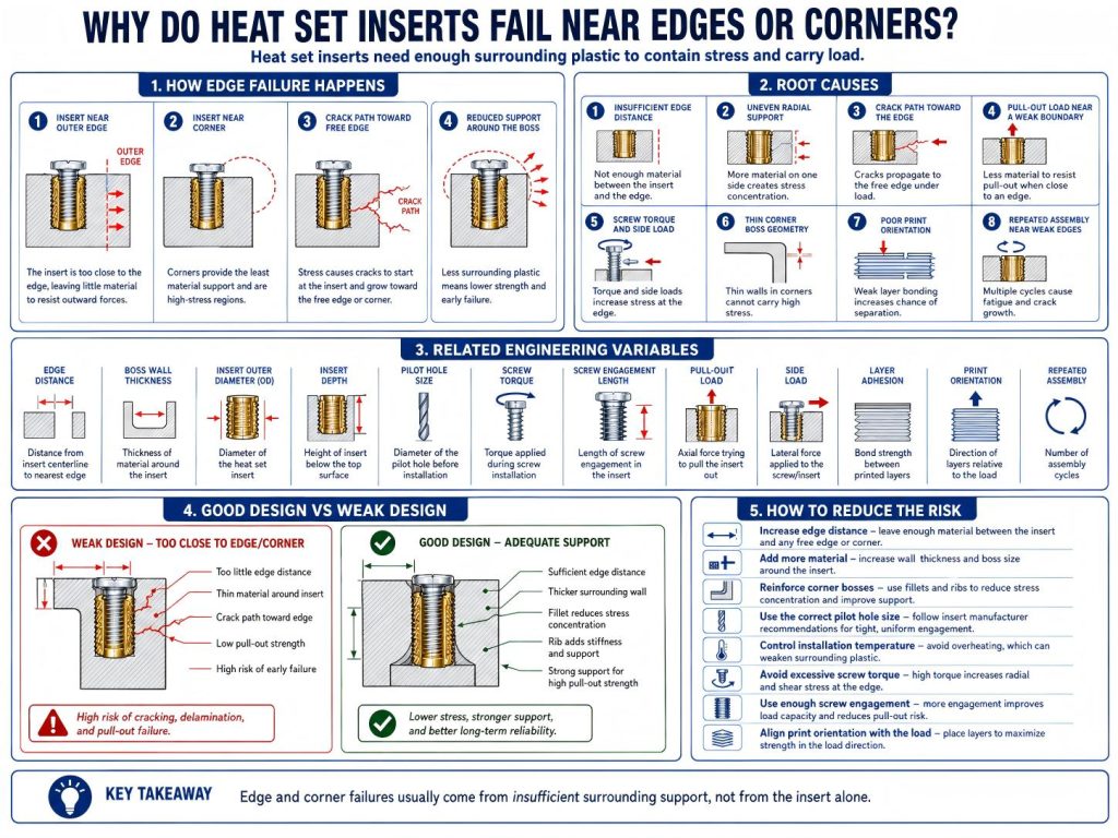
Root Causes
Insufficient Edge Distance
Edge distance is the amount of printed material between the insert and the nearest outer edge.
If this distance is too small, the plastic cannot fully resist radial pressure during installation or screw load during use. The insert may push stress toward the nearest weak edge, creating a crack path or deformation zone.
A boss that works well in the middle of a part may fail near an edge because the surrounding material is no longer symmetrical.
Uneven Radial Support
Heat set inserts create outward pressure during installation.
In a well-supported boss, this pressure is contained by material around the insert. Near an edge or corner, one side of the insert may have much less support than the other side.
This uneven support can cause the boss to ovalize, split, bulge, or crack toward the free edge.
The insert may still appear seated, but the surrounding plastic may already be damaged or weakened.
Crack Path Toward the Edge
A nearby edge can become an easy crack path.
When installation pressure, screw torque, or pull-out load creates stress around the insert, the crack may grow toward the closest free surface. This is common in thin mounting ears, corner bosses, enclosure flanges, brackets, and tabs.
Once a crack reaches the outer edge, the boss loses structural integrity and the insert can loosen, spin, or pull out more easily.
Pull-Out Load Near a Weak Boundary
Pull-out strength depends on how much plastic surrounds and supports the insert.
Near an edge, there is less material available to resist axial load. If the screw pulls on the insert, the nearby edge may tear, split, or deform before the insert itself fails.
This is especially important when inserts are placed in small tabs, brackets, covers, or mounting flanges.
A larger insert may make the problem worse if it leaves even less material between the insert and edge.
Screw Torque and Side Load
Screw tightening creates torque and preload.
If the insert is close to an edge, the surrounding plastic may not distribute the load evenly. Side load, bending load, or off-axis screw force can further concentrate stress toward the nearest weak boundary.
This can cause edge cracking, boss deformation, insert spin, or loss of preload.
Edges and corners are rarely neutral zones. They often magnify stress concentration.
Thin Walls Around Corner Bosses
Corner bosses are common in enclosures and brackets.
However, corner areas may combine several risks: thin wall sections, short edge distance, sharp geometry, limited boss wall thickness, and layer-direction weakness. If the boss is not reinforced, the insert joint may fail even under moderate screw load.
A corner boss should be designed as a reinforced fastening structure, not simply a hole placed near the corner.
Poor Print Orientation
FDM printed parts are directionally strong.
If the insert is near an edge and the load acts across weak layer lines, the edge may split or delaminate around the insert. This can reduce both pull-out strength and torque resistance.
Print orientation matters more near edges because the load path has less surrounding material to spread into.
Repeated Assembly Near Weak Edges
Repeated screw installation and removal can gradually weaken an edge-adjacent insert.
Each assembly cycle applies torque and preload to the same small region of plastic. If the insert is close to an edge, repeated loading can enlarge cracks, reduce support, or cause the boss to deform toward the free boundary.
This is common in serviceable enclosures, brackets, RC parts, drone parts, and electronics covers.
Related Engineering Variables
Heat set insert reliability near edges or corners depends on several connected variables:
- Edge distance
- Boss wall thickness
- Boss outer diameter
- Insert outer diameter
- Insert depth
- Pilot hole size
- Screw tightening torque
- Screw engagement length
- Pull-out load
- Side load
- Installation temperature
- Material brittleness
- Material creep
- Layer adhesion
- Print orientation
- Repeated assembly cycles
- Corner or tab geometry
These variables should be evaluated together. An insert may work well in a thick central boss but fail near an edge because the load path is weaker and less symmetrical.
Edge distance is not just a layout detail. It directly affects fastening reliability.
Engineering Interpretation
Insert failure near edges or corners is usually an edge support and stress concentration problem.
The failure may appear as:
- Boss cracking toward the nearest edge
- Insert loosening from reduced support
- Insert spin from weak radial locking
- Pull-out from insufficient surrounding plastic
- Wall splitting or corner fracture
- Layer separation near the edge
- Loss of screw preload after repeated assembly
These failure modes often overlap.
For example, an insert placed close to a corner may install cleanly at first. Later, screw preload and repeated opening create a small crack toward the edge. Once that crack forms, torque resistance and pull-out strength drop, and the insert may become loose or spin.
This is why edge distance should be considered part of boss design.
A heat set insert needs surrounding plastic, not only a printed hole.
How to Reduce the Risk
To reduce heat set insert failure near edges or corners:
- Increase edge distance where possible.
- Add more material around the insert.
- Use a reinforced boss instead of placing the insert directly in a thin edge.
- Add ribs, fillets, or local thickened pads around corner bosses.
- Use the correct pilot hole size.
- Avoid undersized holes that create excessive radial stress.
- Avoid oversized inserts when edge distance is limited.
- Control installation temperature carefully.
- Avoid excessive screw torque.
- Use enough screw engagement length.
- Align print orientation with expected load direction.
- Avoid placing high-load inserts near unsupported corners.
- Design repeated-service joints with extra edge support.
- Consider smaller inserts if the surrounding structure is limited.
The best solution is usually not simply changing insert type. It is improving the printed structure around the insert.
A reliable edge-adjacent insert joint needs enough surrounding material to contain stress and carry load.
Related InsertGuide Pages
- How to Design Bosses for Heat Set Inserts
- M3 Heat Set Insert Boss Design for 3D Printed Parts
- Why Do Heat Set Inserts Fail in Thin Wall 3D Printed Parts?
- Why Do Bosses Crack Around Heat Set Inserts?
- What Causes Boss Deformation Around Heat Set Inserts?
- Why Do Heat Set Inserts Pull Out of 3D Printed Parts?
- Why Do Heat Set Inserts Spin in 3D Printed Parts?
- Heat Set Insert Hole Size Guide
- Layer Adhesion and Heat Set Insert Strength in 3D Printed Parts
FAQ
How close can a heat set insert be to an edge?
There is no universal distance for every insert and material. The insert should have enough surrounding plastic to resist installation pressure, screw torque, pull-out load, and repeated assembly. If the edge distance is too small, cracking or pull-out risk increases.
Why do inserts crack corners in 3D printed parts?
Inserts crack corners when installation stress or screw load is concentrated toward a nearby weak edge. Thin corner geometry, small edge distance, brittle material, poor hole sizing, and layer orientation can all increase cracking risk.
Can a smaller insert help near an edge?
Sometimes. A smaller insert can reduce radial stress and leave more surrounding plastic, but the printed boss still needs enough wall thickness, edge distance, and load support. A smaller insert alone does not fix weak geometry.