
Introduction
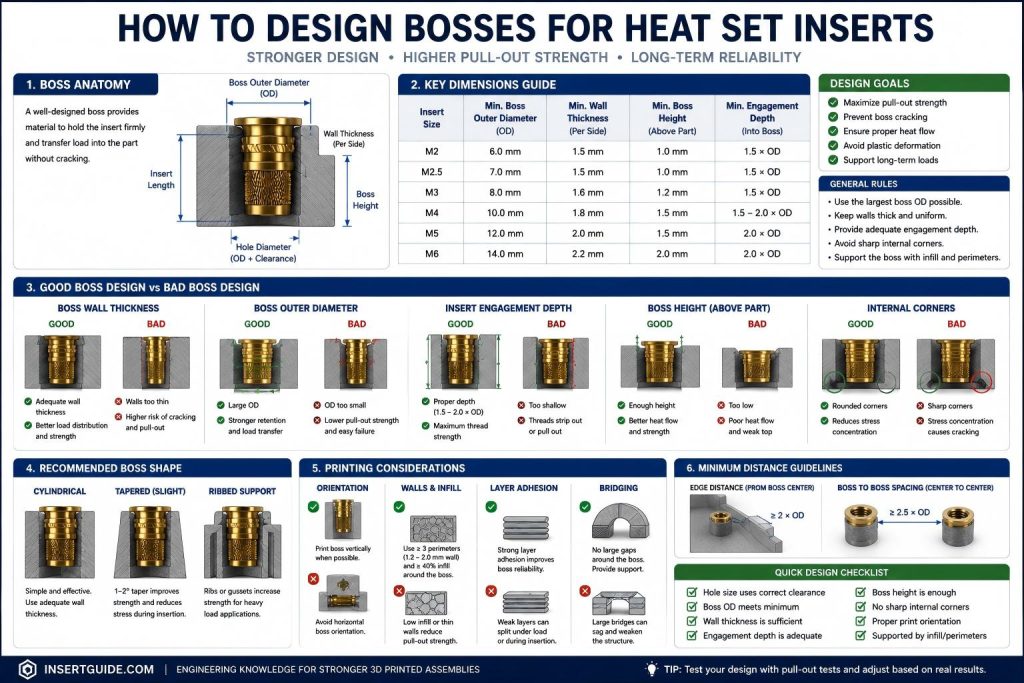
This guide explains how to design bosses for heat set inserts in 3D printed parts, with a focus on wall thickness, boss depth, material behavior, and fastening reliability. A boss is the raised or reinforced feature that holds a heat set insert inside a 3D printed part. In fastening design, the boss is not just a place to put a hole. It is the structure that supports the insert, the screw, and the load carried by the assembly.
A correct hole size is not enough. The boss must be designed as a load-bearing structure.
Heat set inserts rely on the surrounding plastic to resist torque, pull-out force, side loading, and repeated assembly. If the boss is too thin, too shallow, too close to an edge, or poorly supported, the insert may fail even when the hole diameter is correct.
A good boss design should consider insert geometry, boss wall thickness, hole depth, material behavior, edge distance, ribs, layer direction, screw length, and the direction of the load.
For 3D printed parts, boss design is often the difference between an insert that fits and an insert that actually survives real use.
Why Boss Design Matters
Heat set inserts do not create strength by themselves. The brass insert provides a durable internal thread, but the printed boss provides the surrounding structure that keeps the insert in place.
Poor boss design can cause:
- the boss wall to crack during installation
- the insert to spin when the screw is tightened
- the insert to pull out under load
- the boss to deform from heat or pressure
- the screw to bottom out before clamping the assembly
- the joint to loosen after repeated assembly
Many insert failures are not caused by the insert itself. They are caused by weak geometry around the insert.
The boss must provide enough plastic volume for retention, enough wall thickness for strength, enough depth for the insert and screw, and enough support to resist the actual load direction.
Direct Answer: What Makes a Good Boss for Heat Set Inserts?
A good boss for heat set inserts has enough wall thickness around the insert, enough depth below the insert, enough distance from part edges, and enough support to resist pull-out and torque loads.
The boss should be designed around the insert’s outer geometry, not only around the screw size.
A practical way to think about boss design is:
Boss design = insert geometry + hole size + wall thickness + material behavior + load directionDo not treat the boss as a simple cylinder with a hole. Treat it as a small structural feature inside the printed assembly.
Core Boss Design Principles
1. Design Around Insert Geometry
Start with the actual insert dimensions.
Important dimensions include:
- insert outer diameter
- insert length
- knurl diameter
- flange diameter
- recommended hole diameter
- recommended hole depth
- internal thread depth
The screw size alone does not define the boss. An M3 screw only tells you the internal thread size. It does not tell you the insert’s outer diameter, knurl pattern, or required boss size.
Two M3 heat set inserts can require different boss diameters because their external geometry may be different.
The boss should always be designed around the insert body, not only the screw that fits inside it.
2. Provide Enough Boss Wall Thickness
Boss wall thickness is one of the most important parts of insert reliability.
If the wall around the insert is too thin, the boss may crack during installation or split when the screw is tightened. Thin walls also reduce torque resistance and pull-out strength.
Boss wall thickness should be considered together with:
- insert outer diameter
- printed material
- expected screw torque
- layer direction
- edge distance
- repeated assembly requirements
A correct hole size cannot compensate for a weak boss wall. The printed material around the insert must be thick enough to carry installation stress and mechanical load.
3. Make the Boss Deeper Than the Insert
The boss should usually be deeper than the insert length.
During heat installation, softened plastic needs space to move. If the hole stops exactly at the bottom of the insert, displaced plastic may block the internal thread or prevent the insert from seating correctly.
Boss depth should allow for:
- insert length
- displaced plastic
- screw engagement
- clearance below the screw
The screw should engage the insert without bottoming out inside the boss. If the screw reaches the bottom of the hole before clamping the assembly, the joint may feel tight while the parts remain loose.
Boss depth is not only about fitting the insert. It is also about making the screw connection work correctly.
4. Keep Bosses Away From Thin Edges
A boss placed too close to a thin edge is more likely to crack, deform, or lose insert retention.
Heat set insert installation adds both heat and pressure. If there is not enough plastic around the boss, the surrounding wall may split or bulge.
Edge-related failures often appear as:
- side wall cracking
- boss splitting
- insert tilting
- weak pull-out resistance
- reduced torque resistance
If the boss must be close to an edge, the surrounding area should be reinforced with more wall thickness, a wider base, or ribs that connect the boss to the nearby structure.
5. Add Ribs or Support When Needed
Ribs help transfer load from the boss into the surrounding part.
They are especially useful when the boss is tall, narrow, close to a wall, or exposed to side loading. Ribs can improve stability without making the entire part excessively thick.
Ribs are useful for:
- tall bosses
- enclosure mounting points
- brackets
- covers that are removed repeatedly
- parts exposed to vibration or side load
However, ribs should not be too thin. Very thin ribs may print poorly and may not add meaningful strength. A rib should connect cleanly to both the boss and the base structure.
A supported boss is usually more reliable than a tall isolated post.
6. Match Boss Design to Material and Load Direction
Different materials behave differently around heat set inserts.
PLA softens quickly and can deform if too much heat is applied. PETG is tougher, but it may show more plastic flow around the insert. ABS and ASA usually tolerate heat installation better. Nylon is tough but flexible, so weak boss geometry may still allow movement under torque. Resin prints are more brittle and often need thicker support around insert features.
The load direction also matters.
Pull-out loads require enough insert depth and material below the insert. Torque loads require enough wall thickness and good plastic engagement around the insert. Side loads require ribs, wider bases, or integration with nearby walls.
Boss design should always match both the printed material and the expected mechanical load.
Common Boss Design Factors
| Boss Design Factor | Engineering Effect |
|---|---|
| Boss wall thickness | Improves crack resistance and load support |
| Boss outer diameter | Increases surrounding plastic volume and structural rigidity |
| Insert depth | Affects pull-out resistance and load transfer |
| Rib support | Helps distribute stress and reduce deformation |
| Edge distance | Reduces cracking risk near outer walls |
| Print orientation | Influences layer strength around the insert |
| Material stiffness | Affects creep behavior and long-term stability |
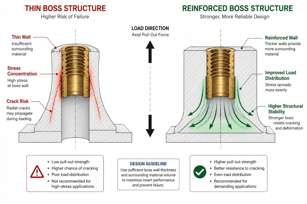
A reliable boss structure depends on the interaction between geometry, material behavior, print orientation, and installation conditions rather than a single dimension alone.
Boss Structure Comparison Diagram
Common Boss Design Mistakes
Mistake 1: Designing Only the Hole
A hole is not enough. The boss around the hole must be strong enough to support the insert and the screw load.
Mistake 2: Making the Boss Wall Too Thin
Thin boss walls can crack during installation, split under screw torque, or fail after repeated assembly.
Mistake 3: Ignoring Boss Depth
If the boss is too shallow, displaced plastic may block the thread or the screw may bottom out before the assembly is clamped.
Mistake 4: Placing the Boss Too Close to an Edge
A boss near a thin edge has less surrounding material to resist cracking, pull-out, and side loading.
Mistake 5: Using Tall Unsupported Bosses
A tall narrow boss can bend, tilt, or deform during insert installation. Ribs or a wider base may be needed.
Mistake 6: Ignoring Material Behavior
PLA, PETG, ABS, nylon, resin, and filled filaments do not behave the same around heat set inserts. Boss geometry should be tested with the actual material.
Failure Examples
Boss Cracks During Insert Installation
A boss may crack during installation when the wall is too thin, the hole is too small, the material is brittle, or too much force is used.
This often happens when the designer focuses only on the pilot hole and does not leave enough surrounding material for the insert to displace plastic safely.
Insert Pulls Out or Spins
An insert may pull out when the boss is too shallow, the hole is too large, or there is not enough plastic around the insert to resist the load.
An insert may spin when the boss wall is too weak, the knurl engagement is poor, or the tightening torque is higher than the surrounding plastic can resist.
Both failures usually point to the same issue: the boss was not designed as a structural feature.
Screw Feels Tight but Assembly Is Loose
A screw can feel tight even when the assembly is not properly clamped.
This can happen when the screw bottoms out inside the boss, when the insert is installed too deep, or when the screw length does not match the insert depth and part thickness.
In this case, the screw is not tightening the assembly. It is only hitting the end of the hole.
Engineering Notes
- Boss design is part of the fastening system, not just part geometry.
- A correct hole size does not guarantee a strong insert joint.
- The boss should be designed around insert geometry, not only screw size.
- Boss wall thickness affects cracking resistance, torque resistance, and pull-out strength.
- Boss depth must allow space for the insert, displaced plastic, and screw engagement.
- Ribs can improve boss stability when the boss is tall, near an edge, or exposed to side loads.
- Material behavior affects how much support the boss needs.
- Layer direction can influence cracking, pull-out behavior, and side-load strength.
- Screw length should be checked before finalizing boss depth.
- Real assembly testing is needed for parts that will be tightened repeatedly or exposed to load.
Related Engineering Factors
Boss design is closely connected to multiple fastening variables in 3D printed assemblies.
Important related engineering factors include:
- hole size and printed tolerance
- insert outer diameter
- boss wall thickness
- insert depth
- pull-out strength
- torque resistance
- installation temperature
- layer adhesion
- material stiffness and creep behavior
A strong boss structure depends on the interaction between the insert geometry, surrounding plastic volume, print orientation, and installation process.
Related engineering guides:
- Heat Set Insert Hole Size Guide
- Pull-Out Strength of Heat Set Inserts in 3D Printed Parts
- Torque Resistance of Heat Set Inserts in 3D Printed Parts
- Layer Adhesion and Heat Set Insert Strength in 3D Printed Parts
- Heat Set Insert Installation Temperature for 3D Printed Parts
FAQ
What is a boss in heat set insert design?
A boss is the raised or reinforced plastic feature that holds a heat set insert inside a 3D printed part. It provides the surrounding structure needed for insert retention and screw load support.
How thick should a boss be for a heat set insert?
The boss should have enough wall thickness to resist cracking, torque, and pull-out loads. The exact thickness depends on insert diameter, material, load direction, and print quality.
How deep should a boss be for a heat set insert?
The boss should usually be deeper than the insert length. It should allow room for the insert, displaced plastic, screw engagement, and clearance so the screw does not bottom out.
Do heat set inserts need ribs around the boss?
Not always. Ribs are useful when the boss is tall, close to an edge, near a thin wall, or exposed to side loads and repeated assembly.
Why do bosses crack around heat set inserts?
Bosses usually crack because the wall is too thin, the hole is too small, the material is brittle, or too much force or heat is used during installation.
Can a correct hole size fix a weak boss?
No. A correct hole size helps insert installation, but it cannot compensate for thin walls, poor layer direction, shallow depth, or weak surrounding geometry.
Should boss design change for PLA and PETG?
Yes. PLA softens quickly and can deform during installation, while PETG may show more plastic flow. Boss wall thickness, heat control, and hole tolerance should be tested for each material.
How do I test a boss design for heat set inserts?
Print the boss geometry, install the insert, let it cool, and test screw engagement, torque resistance, pull-out behavior, cracking, and repeated assembly.
Conclusion
Boss design is one of the most important parts of using heat set inserts in 3D printed parts.
A heat set insert does not create strength by itself. It becomes reliable only when the surrounding boss provides enough wall thickness, depth, plastic volume, and load support.
Good boss design should consider insert geometry, hole size, material behavior, ribs, edge distance, screw length, layer direction, and real assembly loads.
For reliable 3D printed fastening, do not design only a hole. Design the boss as a structural feature.
For final insert selection, compare the exact M3 heat set inserts, insert length, and flange style only after the boss wall thickness, depth, and load direction are defined.
Boss design should also be used together with correct hole sizing. See our heat set insert hole size guide for hole diameter and depth considerations.
For more common engineering questions, see the 3D Printing Fastening FAQ.
Explore More Engineering References
Explore additional engineering guides, fastening references, insert recommendations, and 3D printed assembly knowledge across the InsertGuide engineering network.
Related Engineering Guides
- Ngineering Guides for 3D Printed Fastening
- 3D Printing Fastening FAQ
- 3D Printed Fastening Applications
- How to Choose Heat Set Inserts for 3D Printed Parts
- Heat Set Insert Hole Size Guide
- PLA vs PETG vs ABS for Threaded Inserts
- Why Heat Set Inserts Fail in 3D Printed Parts
- Pull-Out Strength of Heat Set Inserts in 3D Printed Parts
- Torque Resistance of Heat Set Inserts in 3D Printed Parts
- Layer Adhesion and Heat Set Insert Strength in 3D Printed Parts
- Heat Set Insert Installation Temperature for 3D Printed Parts
- Screw Engagement Length for Heat Set Inserts in 3D Printed Parts