
Flanged vs non-flanged heat set inserts for 3D printed parts explains how insert top geometry affects seating depth, surface contact, boss design, screw clamping, and assembly stack-up. Both insert styles can work in printed plastic, but they solve different design problems.
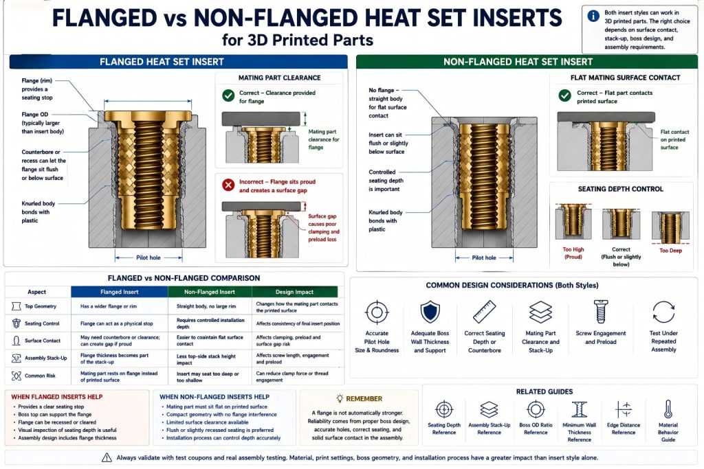
A flanged heat set insert has a wider rim or shoulder near the top of the insert. A non-flanged heat set insert has a straighter body without a large top flange. The difference may look small, but it can change how the insert seats, how the mating part contacts the printed surface, and how screw preload travels through the assembly.
This is an insert type reference, not a product recommendation. The goal is to explain when a flange helps, when it creates interference, and how to design printed bosses around each insert style.
What Is a Flanged Heat Set Insert?
A flanged heat set insert has a wider top feature that can act as a seating stop or load-spreading rim. The flange may help control how far the insert enters the printed boss during installation.
In some designs, the flange sits on top of the printed surface. In other designs, the flange is recessed into a counterbore or pocket so the upper mating part can still sit flat.
The flange can be useful, but it must be included in the assembly design. If the flange is ignored, it may create surface gaps, interfere with mating parts, or change the screw clamping path.
What Is a Non-Flanged Heat Set Insert?
A non-flanged heat set insert has a more continuous cylindrical body without a wide top rim. It can usually sit flush or slightly below the printed surface if the hole depth, seating depth, and installation process are controlled.
Non-flanged inserts are often easier to use in flat mating surfaces because they do not add a raised rim at the top. However, they require better seating control because there may be no flange to act as a physical stop.
If a non-flanged insert is pushed too deep, sits proud, or tilts during installation, the assembly can still fail even though the insert style is compact.
Flanged vs Non-Flanged Inserts: Core Difference
| Feature | Flanged Insert | Non-Flanged Insert |
|---|---|---|
| Top geometry | Has a wider rim or shoulder | Straight or nearly straight body |
| Seating control | Flange may help stop insertion depth | Requires controlled installation depth |
| Surface contact | Can interfere if not recessed or designed around | Usually easier to keep flush with flat surfaces |
| Boss top design | May need counterbore, recess, or clearance | Can use simpler boss top geometry |
| Assembly stack-up | Flange thickness must be included | Less top-side stack effect |
| Common risk | Mating part rests on flange instead of printed surface | Insert may seat too deep or too shallow if process is uncontrolled |
When a Flanged Insert Helps
A flanged insert can be helpful when the design needs a controlled top stop or when the insert should not sink too far into the printed boss. The flange can provide a visible seating reference during installation.
Flanged inserts may be useful when:
- the insert needs a clear seating stop
- the boss has enough top surface area for the flange
- the flange is intentionally recessed into the printed part
- the mating part has clearance for the flange
- the insert is used in a design where top-side contact is acceptable
- the assembly needs easier visual inspection of seating depth
However, the flange must be treated as part of the geometry. It is not invisible. It changes the stack height and the top surface behavior.
When a Flanged Insert Creates Problems
A flanged insert can create problems when the mating part needs to sit flat against the printed surface but the flange sits proud above that surface. In that case, the mating part may contact the flange instead of the printed plastic around it.
This can cause poor clamping even if the screw feels tight. The load path may pass through the flange instead of the intended contact surface.
Flanged inserts can create problems when:
- the flange sits above the printed surface
- the mating part has no clearance pocket for the flange
- the flange creates a surface gap
- the boss top is too small to support the flange
- the flange changes the screw stack-up
- the insert is placed near an edge or thin wall
For seating behavior, see Heat Set Insert Seating Depth Reference for 3D Printed Parts and Should Heat Set Inserts Sit Flush or Below the Surface?.
When a Non-Flanged Insert Helps
A non-flanged insert is often useful when the printed surface must stay flat and the insert should not create a raised top feature. This makes non-flanged inserts common in covers, panels, brackets, and fixture plates where another part must sit directly on the printed surface.
Non-flanged inserts may be useful when:
- the mating part must sit flat
- the boss top should remain simple
- surface clearance is limited
- the insert should sit flush or slightly recessed
- the design uses a flat assembly stack-up
- the installation process can control seating depth
The tradeoff is that the installer must control insertion depth carefully. Without a flange stop, the insert can be pushed too deep if the hole is too deep, the plastic is too soft, or excessive pressure is used.
When a Non-Flanged Insert Creates Problems
A non-flanged insert can fail when seating depth is not controlled. If the insert sits too high, it behaves like a proud insert. If it sits too deep, it may reduce thread access or change screw engagement.
Non-flanged inserts can create problems when:
- the insert is pushed below the intended seating depth
- the hole is too deep or too hot during installation
- the insert tilts because the hole is inaccurate
- the boss has poor wall support
- the screw length does not match the final insert position
- the insert spins because the hole is oversized
For hole accuracy, see Heat Set Insert Pilot Hole Tolerance Reference for 3D Printed Parts.
Surface Contact and Mating Part Fit
The most important question is not whether a flange exists. The important question is whether the mating part contacts the intended printed surface.
If the mating part rests on the flange instead of the surrounding printed surface, the assembly may develop a surface gap. This can reduce preload, create rocking, or make the screw feel tight without creating proper clamping force.
For flat assemblies, a flanged insert often needs one of these design choices:
- a counterbore around the insert so the flange sits below or flush with the surface
- a mating part clearance pocket for the flange
- a boss top geometry that intentionally supports the flange
- a design where the flange itself is part of the contact strategy
If none of these are designed, a non-flanged insert may be easier to integrate.
Assembly Stack-Up Effects
The flange thickness becomes part of the assembly stack-up. If the flange adds height between the insert and the mating part, screw engagement and preload may change.
A non-flanged insert usually has less top-side stack effect, but it still depends on seating depth. If it is recessed too deeply, the screw may need more length. If it is proud, it may create the same kind of surface gap as a poorly designed flanged insert.
For full stack-up behavior, see Heat Set Insert Assembly Stack-Up Reference for 3D Printed Parts.
Boss Design for Flanged Inserts
A flanged insert usually needs a boss top that supports or clears the flange. If the boss top is too narrow, the flange may overhang the plastic or concentrate stress at the rim.
When using flanged inserts, check:
- flange outside diameter
- boss top diameter or width
- whether the flange should sit proud, flush, or recessed
- whether a counterbore is needed
- whether the mating part has enough clearance
- whether the flange changes the screw stack height
For boss sizing, see Boss OD Ratio for Heat Set Inserts in 3D Printed Parts.
Boss Design for Non-Flanged Inserts
Non-flanged inserts usually depend more on controlled hole size, seating depth, and plastic support around the insert body. The boss does not need to support a flange, but it still needs enough wall thickness and edge distance to resist cracking and insert spin.
When using non-flanged inserts, check:
- pilot hole size and tolerance
- hole depth for full seating
- minimum wall thickness around the insert
- edge distance from nearby surfaces
- installation temperature and pressure
- final seating depth after installation
For wall support, see Heat Set Insert Minimum Wall Thickness Reference for 3D Printed Parts and Heat Set Insert Edge Distance Reference for 3D Printed Parts.
Flanged vs Non-Flanged Inserts in Repeated Assembly
Repeated assembly makes insert style more important. A service cover, access panel, fixture plate, or bracket may be opened many times. Each cycle can reveal small seating or contact problems.
A flanged insert may help resist sinking if the flange is supported correctly. But if the flange creates a contact gap, repeated tightening can loosen the assembly. A non-flanged insert may create a cleaner flat surface, but only if seating depth remains consistent.
For repeated-use behavior, see Heat Set Inserts for Repeated Assembly in 3D Printed Parts.
Material Behavior
The material around the insert can change whether a flanged or non-flanged style is easier to use. PLA may crack if the flange or insert body creates high local stress. PETG may deform or creep under clamping load. ABS and ASA may tolerate heat better but still require stable seating and surface contact.
| Material | Flanged Insert Consideration | Non-Flanged Insert Consideration |
|---|---|---|
| PLA | Flange may concentrate stress if boss top is small | Needs controlled installation to avoid cracking |
| PETG | Flange may help seating control but can still lose preload | Flush seating helps, but creep must be tested |
| ABS | Can work if counterbore and boss support are stable | Check shrinkage and seating variation |
| ASA | Useful for exposed parts if flange clearance is designed | Good option when flat surface contact is important |
| Nylon | Flange may help visible seating, but preload relaxation matters | Check long-term movement around the insert |
| Fiber-filled materials | Flange stress concentration can crack brittle local geometry | Needs careful hole tolerance and installation pressure |
For material comparison, see PLA vs PETG vs ABS for Threaded Inserts.
When to Choose a Flanged Insert
A flanged insert is usually a good choice when the design intentionally uses the flange as a seating feature and provides enough geometry to support it.
Choose a flanged insert when:
- a clear seating stop is useful
- the boss top can support the flange
- the flange can sit flush or recessed if a mating part needs flat contact
- the assembly design includes the flange thickness
- visual inspection of seating depth is important
- the mating part has clearance for the flange
When to Choose a Non-Flanged Insert
A non-flanged insert is usually a good choice when the printed surface must remain flat and the design can control installation depth reliably.
Choose a non-flanged insert when:
- the mating part must sit flat against the printed surface
- the boss top should remain simple
- there is no room for flange clearance
- the insert should sit flush or slightly recessed
- the installation process can control depth
- the design prioritizes compact geometry
Common Mistakes
Using a flanged insert without designing flange clearance
If the flange sits proud and the mating part has no clearance, the assembly may clamp against the flange instead of the printed surface.
Assuming a flange always improves strength
A flange can help seating control, but it does not automatically improve pull-out strength or torque resistance. The boss and surrounding plastic still control performance.
Using a non-flanged insert without controlling seating depth
A non-flanged insert can sit too deep or too high if hole depth, temperature, and insertion pressure are not controlled.
Ignoring stack-up changes
Flange thickness, seating depth, mating part thickness, washers, and screw length all affect the final stack-up.
Choosing insert style without testing the real assembly
The correct insert style depends on the printed boss, material, mating part contact, and service condition. A single loose insert test is not enough.
Selection Checklist
- Does the mating part need to sit flat?
- Will the flange sit proud, flush, or recessed?
- Is there clearance for the flange?
- Can the boss top support the flange diameter?
- Will a non-flanged insert need tighter seating control?
- Does the screw still have enough engagement?
- Does the insert style change assembly stack-up?
- Is the boss far enough from edges and thin walls?
- Can the material tolerate installation pressure?
- Has the full assembly been tested after repeated screw cycles?
FAQ
Are flanged heat set inserts better for 3D printed parts?
Not always. Flanged inserts can help control seating depth, but they can also interfere with flat mating surfaces if the flange is not recessed or designed around.
When should I use a flanged heat set insert?
Use a flanged insert when the design can support the flange, include its thickness in the stack-up, and provide clearance or a recess if a flat mating surface is needed.
When should I use a non-flanged heat set insert?
Use a non-flanged insert when compact geometry and flat surface contact are important, and when the installation process can control seating depth accurately.
Can a flanged insert create a surface gap?
Yes. If the flange sits above the printed surface and the mating part has no clearance pocket, the upper part may rest on the flange instead of the printed surface.
Does a flange improve pull-out strength?
A flange may help seating control, but pull-out strength still depends mainly on insert length, knurl engagement, boss geometry, wall thickness, material, and installation quality.
Related Guides
- M3 Brass Heat Set Inserts for 3D Printed Parts
- Short vs Long Heat Set Inserts for 3D Printed Parts
- Heat Set Insert Seating Depth Reference for 3D Printed Parts
- Should Heat Set Inserts Sit Flush or Below the Surface?
- Heat Set Insert Assembly Stack-Up Reference for 3D Printed Parts
- Boss OD Ratio for Heat Set Inserts in 3D Printed Parts
- Heat Set Insert Minimum Wall Thickness Reference for 3D Printed Parts
- PLA vs PETG vs ABS for Threaded Inserts