
Heat Set Insert Edge Distance Reference for 3D Printed Parts explains how much plastic should remain between a heat set insert and nearby edges, corners, thin walls, slots, ribs, or cutouts. Edge distance is one of the most overlooked causes of insert spin, boss cracking, pull-out failure, and long-term preload loss in 3D printed assemblies.
A heat set insert does not only need a correct hole size. It also needs enough surrounding plastic to resist radial expansion, tightening torque, pull-out load, vibration, and repeated screw removal. When the insert is placed too close to an edge, the printed plastic may not have enough material volume to support the knurled insert.
This reference should be used as a practical design guide. It is not an absolute standard, because the safe edge distance depends on insert size, boss geometry, printed material, load direction, print orientation, and assembly conditions.
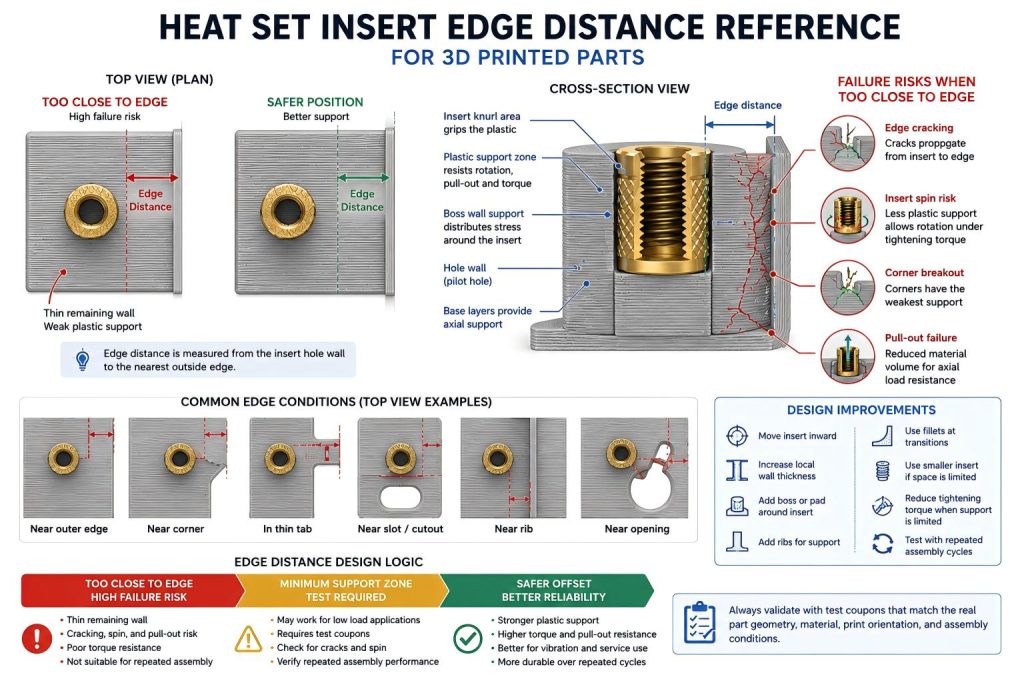
Why Edge Distance Matters
When a heat set insert is installed into printed plastic, the surrounding material must hold the insert from multiple directions. During installation, the heated insert softens and displaces plastic. During screw tightening, the insert must resist rotation, axial pull-out, and local compression.
If the insert is too close to an outside edge, corner, or thin wall, the plastic on one side becomes weak. Instead of forming a balanced support zone around the insert, the part behaves like a partial boss. This increases the risk of cracking, edge breakout, insert tilt, and reduced torque resistance.
In many failed parts, the insert size looks correct and the hole size looks acceptable, but the insert is simply too close to an unsupported boundary.
Edge Distance Is Not the Same as Boss Diameter
Boss outside diameter controls the material around a raised cylindrical boss. Edge distance controls how far the insert or boss is from nearby part boundaries. Both matter, but they solve different problems.
A boss may have a good outside diameter but still fail if it is placed too close to an edge or corner. Likewise, a well-centered insert inside a thick wall may perform better than an insert placed in a narrow tab, even if both use the same hole size and insert size.
For boss sizing, see Boss OD Ratio for Heat Set Inserts in 3D Printed Parts.
Practical Edge Distance Rule
As a practical starting point, the distance from the insert hole edge to the nearest outside edge should be large enough to provide a continuous plastic support zone around the insert. For lightly loaded parts, a smaller distance may work. For high-torque, high-vibration, or repeated-service parts, the edge distance should be more conservative.
A useful design habit is to think in terms of support volume, not only center-to-edge distance. The insert needs enough plastic thickness around its knurled body to resist cracking and rotation.
| Design Condition | Edge Distance Risk | Engineering Recommendation |
|---|---|---|
| Insert centered in a thick boss | Low | Usually acceptable if boss OD, hole size, and hole depth are correct. |
| Insert near a flat outer edge | Moderate | Increase wall thickness or move the insert inward if the part carries torque or pull-out load. |
| Insert near a sharp corner | High | Add more material, fillets, ribs, or move the insert away from the corner. |
| Insert in a thin tab | High | Use a smaller insert, widen the tab, or redesign the fastening location. |
| Insert near a slot, cutout, or opening | High | Treat the opening like an edge and provide extra support around the insert. |
| Insert in a service panel used repeatedly | High | Use larger support geometry and validate repeated screw cycles. |
Center Distance vs Hole Edge Distance
Edge distance can be measured in two ways: from the insert centerline to the nearest edge, or from the pilot hole wall to the nearest edge. For printed plastic design, the second method is often more useful because it directly shows how much plastic remains outside the insert hole.
If the remaining plastic wall outside the hole is too thin, the insert may split the part during installation or screw tightening. This is especially important for M3, M4, and M5 inserts, where the insert diameter and tightening force increase quickly.
Why Inserts Fail Near Edges and Corners
Edges and corners create asymmetric support around the insert. The plastic on the open side cannot resist stress the same way as a fully surrounded boss. This makes several failure modes more likely:
- radial cracking from the insert hole to the outer edge
- corner splitting during screw tightening
- insert rotation because one side has weak plastic support
- pull-out failure under axial load
- localized deformation after repeated screw removal
- preload loss because the surrounding plastic relaxes
For the failure question path, see Why Do Heat Set Inserts Fail Near Edges or Corners?.
Material Behavior Near Edges
Different printed materials respond differently when inserts are placed near edges. PLA may crack sharply when the wall is too thin. PETG may deform or slowly lose preload. ABS and ASA may tolerate more impact, but they still require enough wall thickness and layer support. Nylon may resist cracking better but can allow more movement if the geometry is too flexible.
| Material | Typical Edge Failure Behavior | Design Note |
|---|---|---|
| PLA | Brittle edge cracking | Avoid thin tabs and sharp corners around inserts. |
| PETG | Deformation and preload loss | Increase support volume for repeated assembly. |
| ABS | Layer splitting or local deformation | Use rounded transitions and good print orientation. |
| ASA | Similar to ABS with better outdoor stability | Still needs enough edge distance under screw load. |
| Nylon | Flexible movement around insert | Check torque retention and repeated service cycles. |
| Fiber-filled materials | Stiffer but more direction-sensitive | Avoid placing inserts where layer direction or fiber orientation creates brittle edge paths. |
For material comparison, see PLA vs PETG vs ABS for Threaded Inserts.
Edge Distance and Torque Resistance
Torque resistance depends on how well the plastic around the insert can prevent rotation. When an insert is too close to an edge, the plastic support becomes uneven. The insert may begin to rotate even if the hole size and insert installation appear correct.
This is why inserts near edges should often use lower tightening torque, larger support geometry, or a different fastening layout. Torque should not be increased to compensate for weak edge support. That usually makes the failure worse.
For torque behavior, see Torque Resistance of Heat Set Inserts in 3D Printed Parts and Heat Set Insert Torque Range Reference for 3D Printed Parts.
Edge Distance and Pull-Out Strength
Pull-out strength is also affected by edge distance. If the insert is close to a boundary, the surrounding material has less volume to distribute axial load. Instead of pulling against a full plastic cylinder, the insert may tear out through the closest weak side.
This is especially important for battery covers, service panels, brackets, fixtures, robotics parts, and any assembly where the screw carries repeated load or vibration.
For axial load behavior, see Pull-Out Strength of Heat Set Inserts in 3D Printed Parts.
Thin Walls and Narrow Tabs
Narrow tabs are one of the highest-risk locations for heat set inserts. A tab may look large enough in top view, but the remaining plastic outside the insert hole may be too thin to resist installation pressure or screw tightening.
If an insert must be placed in a tab, the design should use a smaller insert, a wider tab, thicker local reinforcement, rounded transitions, or an alternative fastening strategy. In many cases, moving the screw location inward is stronger than making the screw larger.
For thin-wall failure behavior, see Why Do Heat Set Inserts Fail in Thin Wall 3D Printed Parts?.
Design Improvements for Inserts Near Edges
When an insert must be placed near an edge, the goal is to rebuild the missing plastic support. This can be done through geometry rather than simply increasing insert size.
- Move the insert farther inward when possible.
- Increase the local wall thickness around the insert.
- Add a larger boss or pad around the insert location.
- Add ribs that connect the boss to stronger surrounding geometry.
- Use fillets to reduce sharp stress paths from the boss to the edge.
- Avoid placing inserts at sharp corners unless reinforced.
- Use a smaller insert if the surrounding plastic volume is limited.
- Reduce tightening torque when edge support is weak.
- Validate the design with repeated screw installation cycles.
Common Mistakes
Measuring only from the insert centerline
Centerline distance can hide the real problem. What matters structurally is how much plastic remains outside the insert hole and around the knurled body.
Using a larger insert in a small tab
A larger insert may reduce remaining wall thickness and make the tab more likely to crack. Stronger fastening often comes from better support geometry, not simply a larger thread size.
Ignoring nearby cutouts
A slot, cable opening, vent, clearance pocket, or internal cutout can behave like an edge. Inserts near openings need the same caution as inserts near outside boundaries.
Assuming a successful first assembly means the design is safe
Edge failures often appear after repeated screw removal, vibration, or preload relaxation. A part that survives one tightening cycle may still fail in service.
Practical Test Coupon Method
To validate edge distance, print a test coupon that matches the real part boundary condition. A solid block test is not enough if the final part uses a thin tab, edge boss, corner boss, or insert near a cutout.
The test coupon should reproduce:
- the same insert size and insert length
- the same pilot hole size and hole depth
- the same distance from the insert to the edge
- the same boss outside diameter or local pad geometry
- the same printed material and print orientation
- the same screw engagement length
- the same tightening torque range
- the same repeated assembly condition, if applicable
After testing, inspect the part for radial cracks, insert rotation, edge breakout, boss deformation, and preload loss after repeated cycles.
FAQ
How far should a heat set insert be from the edge of a 3D printed part?
There is no single universal value. The insert should be far enough from the edge to leave a continuous plastic support zone around the hole. Larger inserts, higher torque, repeated assembly, and weaker materials all require more edge distance.
Why do heat set inserts crack near corners?
Corners create stress concentration and asymmetric plastic support. When the insert expands during installation or carries screw torque, the crack often follows the shortest path from the insert hole to the outside corner.
Can I put heat set inserts in thin tabs?
Yes, but thin tabs are high-risk. Use smaller inserts, wider tabs, local reinforcement, lower tightening torque, and repeated-cycle testing. If possible, move the insert inward or redesign the fastening structure.
Does edge distance affect torque resistance?
Yes. Inserts close to edges have less plastic resisting rotation, so they are more likely to spin under tightening torque or repeated screw removal.
Does edge distance affect pull-out strength?
Yes. If the insert is close to an edge, the surrounding plastic has less volume to distribute axial load, making edge breakout or partial pull-out more likely.
Related Guides
- Boss OD Ratio for Heat Set Inserts in 3D Printed Parts
- Heat Set Insert Torque Range Reference for 3D Printed Parts
- Heat Set Insert Hole Size Guide
- How to Design Bosses for Heat Set Inserts
- Pull-Out Strength of Heat Set Inserts in 3D Printed Parts
- Torque Resistance of Heat Set Inserts in 3D Printed Parts
- Why Do Heat Set Inserts Fail Near Edges or Corners?
- Why Do Heat Set Inserts Fail in Thin Wall 3D Printed Parts?