
Heat Set Insert Torque Range Reference for 3D Printed Parts explains how tightening torque should be judged when using threaded brass inserts in printed plastic parts. Torque is not only a screw tightening value. In 3D printed assemblies, it also affects insert spin, boss cracking, thread preload, plastic creep, and long-term fastening reliability.
There is no universal torque value that works for every heat set insert. The safe torque range depends on insert size, screw engagement length, boss geometry, plastic material, print orientation, insert installation quality, and whether the joint is used once or repeatedly serviced.
This reference should be used as a design and testing guide, not as an absolute torque standard. For real assemblies, torque should always be verified with printed test coupons or representative prototype parts.
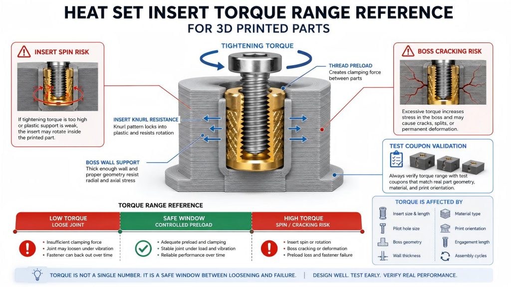
Why Torque Matters in Heat Set Insert Assemblies
When a screw is tightened into a heat set insert, the torque applied at the screw head creates clamping force between the assembled parts. In metal assemblies, this relationship is usually controlled by the screw, thread friction, and contact surfaces. In 3D printed plastic parts, the surrounding plastic often becomes the limiting factor.
If the tightening torque is too low, the joint may loosen during vibration, handling, or repeated use. If the torque is too high, the insert may rotate inside the plastic, the boss may crack, or the printed material may deform around the insert.
This is why torque should be treated as part of the fastening structure, not as a separate screw value.
Torque Is Not Controlled by Insert Size Alone
Insert size gives a useful starting point, but it does not define the final safe torque by itself. An M3 insert in a thick PETG boss may tolerate more tightening torque than an M3 insert placed near the edge of a thin PLA wall. The thread size is the same, but the plastic support condition is different.
For this reason, torque should be evaluated together with:
- insert outside diameter, length, and knurl pattern
- pilot hole size and hole depth
- boss outside diameter and wall thickness
- distance from the insert to nearby edges or corners
- printed material, including PLA, PETG, ABS, ASA, nylon, and filled materials
- print orientation and layer direction around the boss
- screw engagement length inside the insert
- whether the screw is tightened once or removed many times
For hole and boss design, see the Heat Set Insert Hole Size Guide and How to Design Bosses for Heat Set Inserts.
General Torque Sensitivity by Insert Size
The table below gives a practical engineering reference for how torque sensitivity usually changes from M2 to M5 heat set insert assemblies. These are not fixed standards. They are design guidance for early testing and assembly planning.
| Insert Size | Typical Torque Sensitivity | Main Risk | Design Notes |
|---|---|---|---|
| M2 | Very sensitive | Thread stripping, insert spin, small boss cracking | Use light tightening only. Small geometry changes can strongly affect performance. |
| M2.5 | High sensitivity | Insert rotation and plastic deformation | Useful for compact parts, but needs controlled pilot holes and careful screw length. |
| M3 | Moderate sensitivity | Overtightening, boss cracking, preload loss | Common default size for printed assemblies. Still requires test validation. |
| M4 | Lower sensitivity than M3, but higher stress | Boss splitting, local crushing, edge failure | Needs larger boss diameter and enough surrounding plastic volume. |
| M5 | High structural demand | Large boss cracking, plastic creep, insert pull-out under load | Use only when the printed structure has enough material and load path support. |
Why Overtightening Causes Insert Spin
Insert spin occurs when the applied tightening torque exceeds the resistance between the insert knurl and the surrounding plastic. Once the plastic around the knurl yields, the insert can rotate instead of holding the screw preload.
This failure is common when the pilot hole is too large, the insert is overheated during installation, the plastic around the insert is softened or thinned, or the boss wall is too weak to resist rotational load.
Insert spin is not only a torque problem. It is usually a combined result of hole size, heat installation quality, material behavior, and boss geometry.
For a deeper explanation of rotational failure, see Torque Resistance of Heat Set Inserts in 3D Printed Parts.
Why Overtightening Causes Boss Cracking
Boss cracking happens when the plastic around the insert is forced outward or placed under excessive local stress. This can happen during insert installation, screw tightening, or repeated service cycles.
High tightening torque increases radial and axial stress around the insert. If the boss outside diameter is too small, the insert is too close to an edge, or the print layers are poorly oriented, the boss may split even before the screw reaches useful clamping force.
A larger screw does not automatically make the joint stronger. If the printed boss cannot support the insert, a larger insert may simply create a larger failure zone.
For boss wall sizing, see Boss OD Ratio for Heat Set Inserts in 3D Printed Parts.
Material Behavior and Torque Retention
Different 3D printing materials respond differently to tightening torque. The first tightening event may look acceptable, but the joint can still lose preload over time due to plastic creep, heat exposure, vibration, or repeated screw removal.
| Material | Torque Behavior | Common Risk |
|---|---|---|
| PLA | Stiff at room temperature, but brittle and heat-sensitive | Boss cracking, creep near warm environments, sudden fracture |
| PETG | Tougher than PLA, but more prone to creep | Preload loss, slow deformation around the insert |
| ABS | Better temperature resistance than PLA | Layer splitting, deformation if boss geometry is weak |
| ASA | Good outdoor and temperature behavior | Similar design risks to ABS, depending on print quality |
| Nylon | Tough and ductile, but flexible | Preload relaxation, insert movement under repeated load |
| Fiber-filled materials | Stiffer and stronger in some directions | Brittle local cracking, anisotropic failure |
For material comparison, see PLA vs PETG vs ABS for Threaded Inserts.
Practical Torque Check Logic
A useful torque reference process should not begin with a final number. It should begin with failure observation. The goal is to find the torque range where the screw holds the assembly without damaging the printed structure.
Step 1: Confirm Insert Installation Quality
Before testing screw torque, confirm that the insert is installed straight, fully seated, and not overheated. If the insert is already loose after installation, torque testing will not produce meaningful results.
Step 2: Start Below the Expected Assembly Torque
Begin with a low tightening torque and increase gradually. Watch for early warning signs such as plastic whitening, boss swelling, insert movement, screw wobble, or sudden torque drop.
Step 3: Check for Insert Rotation
Mark the insert or the screw head before tightening. If the insert turns with the screw, the plastic is no longer resisting torque properly.
Step 4: Check the Boss After Tightening
Inspect the boss from the side and top. Cracks often begin as small radial lines near the insert or as layer separation around the boss base.
Step 5: Repeat the Tightening Cycle
For serviceable parts, one successful tightening event is not enough. Remove and reinstall the screw multiple times to check whether the insert loosens or the plastic loses clamping support.
Test Coupon Method
The safest way to establish a working torque range is to print a test coupon that matches the real part geometry. A flat block with an insert is not always enough. The coupon should reproduce the same boss diameter, hole depth, wall thickness, material, print orientation, and screw engagement length used in the final design.
A simple test coupon should include:
- the same insert size and insert length
- the same pilot hole diameter and hole depth
- the same boss outside diameter
- the same printed material and print settings
- the same screw size and screw engagement length
- the same assembly stack thickness, if possible
Test at least several samples. A single part may hide variation caused by printing tolerance, hole accuracy, and insertion temperature.
Torque Range Should Be Treated as a Safe Window
The useful tightening torque is not a single magic value. It is a safe window between two limits.
- The lower limit is the torque needed to keep the joint from loosening.
- The upper limit is the torque that causes insert spin, boss cracking, plastic deformation, or long-term preload loss.
A good printed insert design has enough margin between these two limits. If the part begins to fail only slightly above the required tightening torque, the design is too fragile for reliable assembly.
Warning Signs That Torque Is Too High
Reduce torque or redesign the insert structure if you observe any of the following:
- the insert rotates while tightening the screw
- the boss shows radial cracks after tightening
- the screw suddenly loses resistance during tightening
- the insert pulls upward or shifts position
- the plastic around the boss turns white or deforms
- the joint feels tight at first but loosens after a short time
- the screw cannot be removed without moving the insert
Design Rules for Better Torque Reliability
To improve torque reliability in heat set insert assemblies, the design should support the insert from multiple directions. The screw, insert, boss, and surrounding printed structure must work as one system.
- Use a pilot hole size recommended for the specific insert and material.
- Provide enough hole depth so the insert is fully seated without bottoming out.
- Use a boss outside diameter large enough to resist radial cracking.
- Avoid placing inserts too close to part edges or corners.
- Use enough screw engagement length, but do not bottom the screw inside the hole.
- Use washers or larger contact surfaces when clamping soft printed parts.
- Use lower torque and thread-locking strategy when vibration is present.
- Validate repeated assembly cycles if the part will be serviced often.
For screw engagement planning, see Screw Engagement Length for Heat Set Inserts in 3D Printed Parts.
Common Mistakes
Using metal fastener torque values directly
Metal assembly torque values are often too aggressive for printed plastic insert joints. The limiting factor is usually the plastic structure, not the screw thread.
Assuming a larger insert always allows higher torque
A larger insert also needs a larger boss, more material around the hole, and better load support. Without enough plastic volume, the larger insert can crack the part faster.
Ignoring repeated service cycles
A screw may tighten successfully once, but repeated removal can weaken the insert interface. Service panels, lids, access covers, and modular assemblies need cycle testing.
Testing inserts in solid blocks only
Solid test blocks often perform better than real parts. Real parts may include thin walls, edges, ribs, corners, and unsupported boss geometry.
FAQ
Is there a standard torque value for heat set inserts in 3D printed parts?
No single standard torque value applies to all heat set insert assemblies. The safe torque depends on insert size, plastic material, boss geometry, hole size, screw engagement, and installation quality.
Why does my insert spin when I tighten the screw?
Insert spin usually means the applied torque is higher than the plastic can resist. It may also indicate an oversized hole, overheated installation, weak boss geometry, or poor material support around the insert.
Can I use normal metal screw torque charts?
Metal screw torque charts should not be used directly for 3D printed insert joints. Printed plastic often fails before the screw or metal insert reaches typical metal assembly torque values.
How should I test tightening torque?
Print a test coupon that matches the real part geometry, then tighten gradually while checking for insert rotation, boss cracking, plastic deformation, and preload loss after repeated cycles.
Does PETG hold torque better than PLA?
PETG is usually tougher than PLA, but it can creep more over time. PLA may feel stiff during tightening, but it is more brittle and heat-sensitive. The better material depends on the load, temperature, and service condition.
Related Guides
- Torque Resistance of Heat Set Inserts in 3D Printed Parts
- Boss OD Ratio for Heat Set Inserts in 3D Printed Parts
- Heat Set Insert Hole Size Guide
- Heat Set Insert Hole Depth Chart for 3D Printed Parts
- How to Design Bosses for Heat Set Inserts
- Screw Engagement Length for Heat Set Inserts in 3D Printed Parts
- Pull-Out Strength of Heat Set Inserts in 3D Printed Parts
- PLA vs PETG vs ABS for Threaded Inserts
Related Decision Resources
For insert selection, tool choice, and supplier comparison, use these decision-focused references after the engineering requirements are defined.