
Torque resistance heat set inserts performance is one of the key requirements for reliable threaded connections in 3D printed parts.
When a screw is tightened into an insert, the insert must resist rotational force. If the surrounding plastic cannot hold the insert firmly, the insert may spin inside the printed boss instead of tightening the joint.
Engineering Definition
Torque resistance is the ability of a heat set insert to resist rotational movement inside the surrounding printed plastic during screw tightening or mechanical loading.
In 3D printed parts, torque resistance depends on insert geometry, hole tolerance, boss rigidity, material behavior, layer adhesion, and installation conditions.
This failure is common in 3D printed parts.
The screw may feel tight at first, but after one or two turns, the insert starts rotating with the screw. Once this happens, the threaded joint loses its function. In many cases, the insert becomes difficult to remove, repair, or reuse.
Torque resistance is not only controlled by the insert’s knurling. It is also controlled by the printed structure around the insert.
A heat set insert resists torque through a combination of:
- insert outer geometry
- knurl design
- hole size
- boss wall thickness
- material stiffness and toughness
- plastic flow during installation
- insertion depth
- print orientation
- layer bonding
- screw tightening force
In 3D printed parts, torque resistance should be understood as a structural property, not just an insert specification.
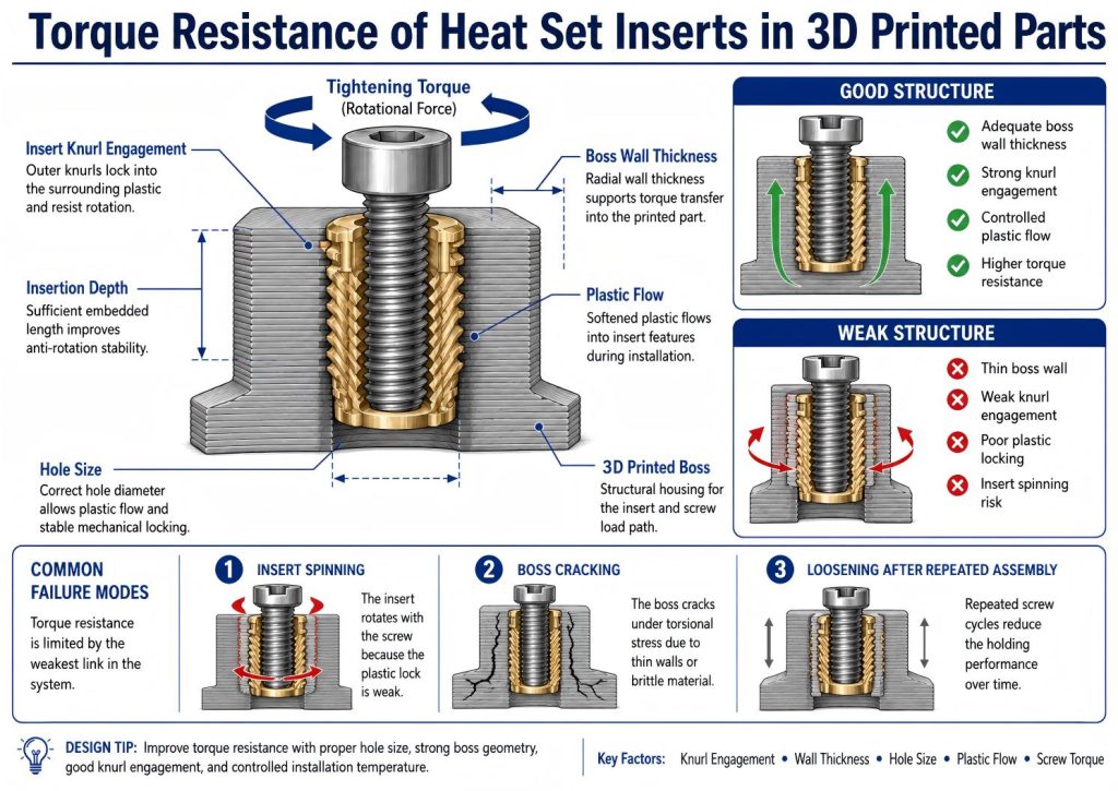
What Torque Resistance Means
Torque resistance describes how well an insert resists rotation when a screw is tightened.
It answers a simple question:
Will the insert stay locked in place, or will it spin inside the printed part?
This is different from pull-out strength.
Pull-out strength measures how much axial force the insert can resist before being pulled out of the part. Torque resistance measures how much rotational force the insert can resist before it turns inside the plastic.
A reliable insert joint needs both.
An insert that resists pull-out well may still spin if the plastic around the knurled surface is weak. An insert that resists spinning may still fail in pull-out if the boss is too shallow or the load direction is poorly supported.
For functional assemblies, both forces must be considered.
Why Inserts Spin in 3D Printed Parts
Insert spinning usually happens when the insert surface cannot lock firmly into the surrounding plastic.
During heat set installation, the insert is heated and pressed into a printed hole. The plastic around the hole softens, flows around the knurled or textured surface, and then cools.
If this process works correctly, the plastic forms a mechanical lock around the insert.
If it does not, the insert may rotate under screw tightening torque.
Common causes include:
- hole diameter too large
- installation temperature too low
- insufficient plastic flow around knurls
- boss wall too thin
- weak layer adhesion
- brittle material cracking around the insert
- insert installed too shallow
- excessive screw tightening torque
- poor insert geometry for plastic locking
Most spinning failures are not caused by one factor alone. They usually happen when several small weaknesses combine.
The Role of Insert Knurling
Most heat set inserts have external knurls, grooves, or ridges.
These features help the insert grip the plastic after installation.
Knurling is important for torque resistance because it creates mechanical interference between the insert and the surrounding material. When the screw applies rotational force, the plastic must resist the insert’s attempt to turn.
However, knurling only works if plastic flows properly into the surface features.
If the hole is too large, there may not be enough plastic contact.
If the installation temperature is too low, the plastic may not flow into the knurls.
If the material is too brittle, it may crack instead of forming around the insert.
This is why insert geometry alone does not guarantee torque resistance. The printed plastic must form a complete grip around the insert.
Hole Size and Torque Resistance
Hole size has a direct effect on torque resistance.
If the hole is too large, the insert may slide into place easily, but there will be limited plastic displacement. The knurled surface may not fully engage with the plastic.
This often leads to low torque resistance.
If the hole is too small, the insert may require too much force during installation. The boss may crack, or the plastic may be pushed outward instead of flowing evenly around the insert.
Both conditions are bad.
A good hole size allows controlled plastic flow.
The insert should enter the hole with heat, not brute force. The plastic should soften, move around the insert texture, and then cool into a locked shape.
For torque resistance, the goal is not just a tight fit. The goal is a stable mechanical lock.
Torque Resistance Relationships
| Engineering Factor | Effect on Torque Resistance |
|---|---|
| Knurl geometry | Improves rotational grip inside the plastic |
| Hole tolerance | Controls interference fit and insert stability |
| Boss wall rigidity | Reduces deformation under tightening load |
| Material stiffness | Affects resistance to rotational movement |
| Layer adhesion | Influences structural support around the insert |
| Installation temperature | Changes plastic flow and bonding quality |
| Repeated tightening cycles | Can reduce long-term rotational stability |
Torque resistance depends on the interaction between insert geometry, surrounding plastic rigidity, material behavior, and repeated mechanical loading conditions.
Boss Wall Thickness and Torque Resistance
A thin boss cannot resist rotational stress well.
When torque is applied to the screw, the insert transfers that twisting force into the boss wall. If the boss wall is too thin, the plastic around the insert may deform, crack, or split.
In many failures, the insert does not spin because the insert is poor. It spins because the boss structure around it is too weak.
A stronger boss improves torque resistance by giving the insert more surrounding material to push against.
Good boss design should provide:
- enough wall thickness around the insert
- enough depth to support the insert body
- a stable base connected to the main part
- smooth transitions to reduce cracking
- sufficient printed perimeters around the hole
Torque resistance depends on the boss acting like a structural anchor, not just a plastic sleeve.
Material Behavior Under Torque
Different 3D printing materials respond differently to tightening torque.
PLA is stiff and dimensionally stable, but it can crack if the boss wall is thin or the hole is too small. It may also soften under heat or long-term service conditions.
PETG is tougher and more ductile. It can absorb some deformation, which helps prevent cracking. However, it may deform under repeated tightening or long-term stress.
ABS has better heat resistance and can work well with heat set inserts, but print quality and layer adhesion are important.
Nylon can provide strong insert joints because of its toughness, but it requires careful control of moisture, printing conditions, and hole dimensions.
For torque resistance, stiffness alone is not enough. The material must be able to grip the insert without cracking, creeping, or losing shape.
Installation Temperature and Plastic Flow
Installation quality strongly affects torque resistance.
If the insert is not hot enough, the plastic may not soften properly. The insert may be forced into the hole, cutting or compressing the plastic instead of allowing it to flow around the knurls.
This creates a weak lock.
If the insert is too hot, the plastic may over-soften. The hole may become enlarged, the boss may deform, and the material around the insert may lose structure.
The best installation process allows the insert to move slowly into the hole as the plastic softens. After insertion, the plastic should cool while holding the insert in position.
Good installation is controlled melting, not forced insertion.
For torque resistance, the cooling phase matters too. If the insert is disturbed before the plastic solidifies, the mechanical lock can weaken.
Screw Tightening and Over-Torque
Even a well-installed insert can fail if the screw is over-tightened.
Torque resistance has a limit.
If the screw tightening torque exceeds the strength of the insert-plastic interface, the insert may spin. If the boss is brittle, it may crack instead.
This is especially important in small insert sizes such as M2, M2.5, or M3. Small inserts have limited surface area, and the surrounding printed boss may be easy to damage.
For functional assemblies, screw torque should match:
- insert size
- material type
- boss geometry
- screw engagement length
- expected service load
- number of assembly cycles
A heat set insert is not a license to tighten without control. It creates a reusable thread, but the plastic structure still defines the limit.
Print Orientation and Layer Effects
Torque loads are not only carried by the plastic around the insert. They are also affected by how the part was printed.
If the boss walls are formed by weak layer bonding, torque may cause the structure to split along layer lines.
If the boss is printed with continuous perimeters around the insert, torque resistance can improve.
Print orientation can also affect how torque stress travels from the insert into the rest of the part.
A boss printed upright may behave differently from a boss printed sideways. The best orientation depends on how the screw is loaded and how the part will be assembled.
For critical parts, insert torque performance should be tested in the actual print orientation.
Common Torque Failure Modes
Insert Spins During Screw Tightening
This is the most direct torque failure.
The screw starts to tighten, but the insert rotates inside the printed hole.
Possible causes include:
- hole too large
- weak plastic flow during installation
- insufficient knurl engagement
- installation temperature too low
- screw tightened beyond the joint capacity
Once the insert spins, the printed hole may become enlarged, making repair difficult.
Boss Cracks Around the Insert
In this case, the insert may not spin immediately. Instead, the boss cracks because the surrounding material cannot resist the twisting stress.
Possible causes include:
- boss wall too thin
- hole too small
- brittle material
- excessive insertion pressure
- too much screw tightening torque
This failure means the insert grip exceeded the strength of the boss.
Insert Loosens After Repeated Assembly
Some inserts hold well at first but loosen after repeated screw cycles.
Possible causes include:
- plastic creep
- repeated tightening and loosening
- thermal cycling
- screw over-tightening
- weak material recovery
- insufficient insert depth
Reusable joints need better design margins than one-time assemblies.
Insert Spins Under Service Load
In some assemblies, the insert does not fail during installation or first tightening. It spins later during vibration, impact, or mechanical load.
Possible causes include:
- dynamic loading
- low boss stiffness
- weak material under heat
- poor load distribution
- insufficient torque safety margin
This is common in functional prototypes, robotics, fixtures, brackets, and enclosures that experience repeated mechanical stress.
How to Improve Torque Resistance
Torque resistance can be improved through both design and process control.
Useful strategies include:
- choose inserts with suitable knurl geometry
- use the correct hole size for the material
- increase boss wall thickness
- increase boss depth when space allows
- add fillets at the boss base
- use more perimeters around insert holes
- avoid placing inserts too close to part edges
- control installation temperature
- insert slowly and vertically
- allow the plastic to cool before tightening screws
- avoid over-tightening small screws
- test critical joints before final production
The strongest torque-resistant joint is not created by one feature. It is created by matching insert geometry, plastic flow, boss design, and screw torque.
Torque Resistance and Pull-Out Strength Work Together
Torque resistance and pull-out strength are different, but they are connected.
A good insert joint must resist both turning and pulling.
If torque resistance is weak, the insert spins when the screw is tightened.
If pull-out strength is weak, the insert may be pulled out under load.
If boss design is weak, the printed structure may crack before either limit is reached.
This is why insert design should be treated as a complete fastening system.
The insert is only one part of the joint.
The boss, hole, material, print settings, and screw all decide whether the connection will survive real use.
Practical Design Principle
The most important torque question is not:
Can the screw tighten into the insert?
The better question is:
Can the printed plastic stop the insert from rotating when the screw applies torque?
That difference matters.
A screw can thread smoothly into a poorly supported insert. But when tightening force increases, the insert may still spin.
Reliable torque resistance begins with the structure around the insert.
The hole must allow plastic flow.
The boss must provide enough wall strength.
The material must grip without cracking.
The installation process must create a mechanical lock.
The screw torque must stay within the capacity of the printed joint.
When these conditions work together, heat set inserts can create strong, reusable threaded connections in 3D printed parts.
When one condition is ignored, the insert may become the strongest part of a weak structure.
Related Engineering Factors
For a size-specific torque node, see M3 heat set insert torque resistance.
For a size-specific torque node, see M4 heat set insert torque resistance.
Torque resistance depends on how effectively the insert can resist rotational movement inside the surrounding printed structure.
Important related engineering factors include:
- insert knurl geometry
- printed hole tolerance
- interference fit
- boss wall rigidity
- material softening behavior
- installation temperature
- rotational stress distribution
- layer adhesion strength
- repeated tightening cycles
- long-term creep deformation
Poor torque resistance often results in insert spinning, gradual loosening, or permanent damage to the surrounding plastic structure.
Related engineering guides:
- How to Choose Heat Set Inserts for 3D Printed Parts
- Heat Set Insert Hole Size Guide
- How to Design Bosses for Heat Set Inserts
- PLA vs PETG vs ABS for Threaded Inserts
- Why Heat Set Inserts Fail in 3D Printed Parts
- Pull-Out Strength of Heat Set Inserts in 3D Printed Parts
- Layer Adhesion and Heat Set Insert Strength in 3D Printed Parts
- Heat Set Insert Installation Temperature for 3D Printed Parts
Common Rotational Failure Signals
Common rotational failure signals in heat set insert assemblies include:
- inserts spinning during screw tightening
- gradual loosening after repeated assembly cycles
- reduced torque stability over time
- softened plastic around the insert
- cracking near the boss wall
- rotational movement under moderate load
- damaged surrounding layers after overtightening
These failures are often related to hole tolerance, boss rigidity, material behavior, installation temperature, and repeated mechanical stress.
FAQ
What does torque resistance mean for heat set inserts?
Torque resistance describes how well a heat set insert resists rotation when a screw is tightened. In 3D printed parts, it depends on the insert geometry, hole size, boss wall thickness, plastic flow, material behavior, print orientation, and screw tightening force.
Why do heat set inserts spin in 3D printed parts?
Heat set inserts usually spin when the surrounding plastic does not form a strong mechanical lock around the insert. Common causes include oversized holes, low installation temperature, weak knurl engagement, thin boss walls, poor layer adhesion, or excessive screw torque.
Does hole size affect torque resistance?
Yes. If the hole is too large, the insert may not engage enough plastic. If the hole is too small, the boss may crack during installation. A correct hole size allows softened plastic to flow around the insert knurls and create a stable mechanical lock.
How does boss design improve torque resistance?
A stronger boss improves torque resistance by giving the insert more material to push against during screw tightening. Adequate boss wall thickness, sufficient depth, more perimeters, and a stable connection to the main part help prevent insert spinning and boss cracking.
How can I prevent heat set inserts from spinning?
Heat set inserts can be prevented from spinning by using the correct hole size, choosing suitable insert knurling, increasing boss wall thickness, controlling installation temperature, allowing the plastic to cool before tightening screws, and avoiding excessive screw torque.
Related Engineering Guides
- Ngineering Guides for 3D Printed Fastening
- 3D Printing Fastening FAQ
- 3D Printed Fastening Applications
- How to Choose Heat Set Inserts for 3D Printed Parts
- Heat Set Insert Hole Size Guide
- How to Design Bosses for Heat Set Inserts
- PLA vs PETG vs ABS for Threaded Inserts
- Why Heat Set Inserts Fail in 3D Printed Parts
- Pull-Out Strength of Heat Set Inserts in 3D Printed Parts
- Layer Adhesion and Heat Set Insert Strength in 3D Printed Parts
- Heat Set Insert Installation Temperature for 3D Printed Parts
- Screw Engagement Length for Heat Set Inserts in 3D Printed Parts
Related Decision Resources
In practical torque resistance selection scenarios, compare best heat set insert options, brand and tolerance consistency, and short vs long insert length after the boss support, hole fit, and repeated torque load are defined.