
Boss OD ratio for heat set inserts is one of the most important geometry checks in 3D printed fastening design. The boss outside diameter should not be chosen only from the screw size. It must be designed around the heat set insert outside diameter, printed hole size, wall thickness, material behavior, edge distance, and expected load.
If the boss outside diameter is too small, the insert may crack the boss during installation, deform the printed wall, lose torque resistance, or fail under pull-out load. If the boss is oversized without purpose, the part may become bulky, heavy, or difficult to fit into compact assemblies.
This reference explains how to think about boss OD ratio for heat set inserts in 3D printed parts. It covers insert outside diameter, boss outside diameter, wall thickness, edge distance, M2 through M5 insert sizing logic, material behavior, and common boss-related failure modes.
Boss OD ratio is not universal. Different insert sizes, knurl patterns, printed materials, layer orientations, and load conditions require different support geometry. Always check the actual insert datasheet, printed hole behavior, and application load before finalizing the boss.
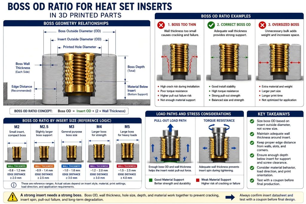
What Boss OD Ratio Means
Boss OD ratio describes the relationship between the outside diameter of the heat set insert and the outside diameter of the printed boss that supports it.
In simple terms:
Boss OD ratio = boss outside diameter compared with insert outside diameter.
The insert outside diameter controls how much material is displaced during heat installation. The boss outside diameter controls how much plastic remains around the insert to resist cracking, pull-out, torque, and long-term deformation.
A boss is not just a cylinder around a hole. It is the local load-bearing structure that allows the metal insert to work inside a printed plastic part.
Why Boss OD Should Be Based on Insert OD, Not Screw Size
A common mistake is to design the boss around the screw size. For example, a designer may think an M3 screw only needs a small boss because the screw diameter is small. But a heat set insert is much larger than the screw thread.
The printed boss must support:
- the printed hole diameter
- the insert outside diameter
- the knurled or patterned insert body
- plastic displacement during heat installation
- screw tightening torque
- pull-out load
- local stress around the boss wall
This is why boss OD should start from the insert outside diameter, not from the screw thread diameter.
For broader boss design principles, see How to Design Bosses for Heat Set Inserts.
Basic Boss OD Ratio Logic
A practical starting point is to think in three layers:
- Insert OD: the largest outside diameter of the heat set insert body.
- Wall thickness: the plastic thickness remaining around the insert hole.
- Boss OD: the final outside diameter of the printed boss.
The relationship can be understood as:
Boss outside diameter = insert outside diameter + two sides of surrounding wall thickness.
This is not a fixed formula for every design, but it gives a useful way to think about boss sizing. If the insert outside diameter increases, the boss outside diameter usually needs to increase as well.
Example Boss OD Ratio Reference
The following chart gives practical reference logic for common insert sizes. These values are not universal dimensions. They are engineering reference ranges for understanding how insert size and boss support relate in 3D printed parts.
| Insert Size | Typical Insert OD Logic | Boss OD Design Logic | Common Risk if Boss Is Too Small |
|---|---|---|---|
| M2 | Small insert OD, compact body | Needs enough wall thickness despite small part size | Boss cracking, insert spin, weak edge support |
| M2.5 | Middle size between M2 and M3 | Useful for compact brackets but still needs real boss support | Thin wall cracking, poor torque resistance |
| M3 | Common general-purpose insert size | Boss OD should support repeated assembly and normal screw torque | Insert loosening, boss deformation, pull-out failure |
| M4 | Larger structural insert body | Requires larger boss OD, more wall thickness, and better edge distance | Boss splitting, edge breakout, high local stress |
| M5 | Large insert body for stronger fastening | Needs substantial surrounding plastic and strong load path | Large crack propagation, weak boss base, structural failure |
For size-specific reference pages, see M2 Heat Set Insert Dimensions Reference for 3D Printed Parts, M2.5 Heat Set Insert Dimensions Reference for 3D Printed Parts, M3 Heat Set Insert Dimensions Reference, M4 Heat Set Insert Dimensions Reference for 3D Printed Parts, and M5 Heat Set Insert Dimensions Reference for 3D Printed Parts.
Boss Wall Thickness Around the Insert
Boss wall thickness is the plastic thickness between the insert hole and the outside of the boss. It is one of the most important parts of boss OD ratio.
If wall thickness is too low, the boss may:
- crack during insert installation
- bulge outward from heat and pressure
- lose torque resistance
- fail near an edge or corner
- deform under screw preload
- weaken after repeated assembly
Wall thickness should be checked around the largest insert outside diameter, not only around the printed hole diameter. Larger inserts need more wall support because they displace more material and can carry higher tightening forces.
Boss OD and Printed Hole Size
Printed hole size affects boss OD because the hole removes material from the center of the boss. The boss must retain enough surrounding plastic after the hole is printed and after the insert is installed.
If the hole is too large, the insert may not grip properly. If the hole is too small, the insert may push too much material outward and crack the boss. Either condition can make the boss OD ineffective.
A strong-looking boss can still fail if the hole size is wrong.
For hole sizing rules, see the Heat Set Insert Hole Size Guide.
Boss OD and Hole Depth
Boss OD should be considered together with hole depth. A boss may have enough diameter, but still fail if the hole is too deep, too shallow, or leaves too little material below the insert.
The boss should provide:
- enough depth for full insert seating
- enough material below the insert if the hole is blind
- enough wall thickness around the insert body
- enough screw clearance to avoid bottoming
- enough structural support for pull-out and torque loads
If a boss is tall but thin, it may crack. If a boss is wide but shallow, it may not support the insert well. Boss OD and boss depth must work together.
For depth reference, see Heat Set Insert Hole Depth Chart for 3D Printed Parts.
Boss OD and Edge Distance
Boss outside diameter is not only about the boss itself. It also affects edge distance. If the boss is too close to a part edge, slot, cutout, or corner, the surrounding load path may be weak even if the boss appears large enough.
Edge-related problems include:
- boss cracking toward the nearest edge
- wall breakout during screw tightening
- insert pull-out near corners
- thin wall deformation
- loss of torque resistance due to asymmetric support
If the insert is close to an edge, the boss may need more local reinforcement, more radius around corners, or a different insert location.
For edge-related failure logic, see Why Do Heat Set Inserts Fail Near Edges or Corners?.
Boss OD and Pull-Out Strength
Pull-out strength depends on how well the insert is supported along its length and how the load transfers from the screw into the surrounding plastic. Boss OD affects pull-out strength because it controls how much material can resist the load around the insert.
Pull-out strength is affected by:
- insert length
- insert outside diameter
- boss outside diameter
- boss wall thickness
- hole depth
- material behavior
- print orientation
- load direction
A larger boss can help distribute load, but it cannot compensate for poor hole size, weak material, shallow insert depth, or poor layer orientation.
For deeper background, see Pull-Out Strength of Heat Set Inserts in 3D Printed Parts.
Boss OD and Torque Resistance
Torque resistance describes how well the insert resists spinning inside the printed boss during screw tightening. Boss OD affects torque resistance because the surrounding plastic must resist rotational force around the knurled insert body.
A boss with too little wall thickness may allow:
- insert spin during tightening
- plastic deformation around the knurls
- loss of clamp force
- threaded joint loosening after service
- damage during repeated screw removal
Torque resistance is especially important in motor mounts, fixtures, repeated assembly structures, and service panels.
For deeper background, see Torque Resistance of Heat Set Inserts in 3D Printed Parts.
Boss OD and Material Behavior
Different 3D printing materials need different boss support. The same boss OD ratio may work in one material and fail in another.
PLA is stiff and dimensionally stable, but it can crack if the boss wall is thin or the hole is too tight. PETG is tougher, but it can creep under sustained screw preload. ABS can tolerate installation heat better than PLA, but still depends on wall thickness and hole fit. Nylon and carbon fiber nylon may provide better toughness, but printed tolerance, moisture behavior, and fiber-filled material behavior still matter.
Boss OD should be checked together with material stiffness, ductility, creep, heat behavior, and expected service load.
For material comparison, see PLA vs PETG vs ABS for Threaded Inserts.
Boss OD Ratio by Application Type
The required boss OD ratio depends on how the insert joint will be used. A small electronics cover does not need the same support geometry as a motor bracket or fixture plate.
| Application Type | Boss OD Priority | Design Concern |
|---|---|---|
| Small electronics cover | Compact but not too thin | Prevent cracking and thread loosening during service. |
| Sensor or camera mount | Stable enough for repeated adjustment | Prevent insert spin and alignment drift. |
| Battery service cover | Balanced with internal clearance | Prevent thin wall failure and screw contact with internal parts. |
| Motor mounting bracket | High stiffness and vibration support | Prevent preload loss, boss cracking, and insert movement. |
| Fixture or jig | Stronger boss support | Resist repeated assembly, clamp loads, and pull-out force. |
For application examples, see Heat Set Inserts for High-Vibration Motor Mounting Brackets and Heat Set Inserts for Printed Jigs with Replaceable Wear Plates.
Common Boss OD Ratio Mistakes
Designing the Boss Around the Screw Thread
The screw thread is smaller than the insert body. Boss geometry should be based on the insert outside diameter and the printed hole, not only on the screw size.
Making the Boss Too Thin
A thin boss may crack during heat insertion or screw tightening. This is especially common in compact parts and small service panels.
See also: Why Do Bosses Crack Around Heat Set Inserts?
Placing the Boss Too Close to an Edge
A boss near an edge may have enough diameter on paper, but not enough surrounding load path in the actual part.
Using the Same Boss OD for Every Material
A boss size that works in PETG may crack in PLA or creep under long-term load. Material behavior matters.
Increasing Insert Size Without Increasing Boss Support
Moving from M3 to M4 or M5 without increasing boss diameter and wall thickness can create a stronger metal insert inside a weaker plastic structure.
Ignoring Hole Depth
Boss OD alone is not enough. The insert also needs enough depth, material below the insert, and screw clearance.
Recommended Boss OD Design Checks
Before finalizing boss OD for a heat set insert, check the following:
- Confirm the actual insert outside diameter from the manufacturer datasheet.
- Confirm the recommended printed hole size.
- Check remaining boss wall thickness around the insert.
- Check boss depth and hole depth.
- Check edge distance from the boss to nearby walls, corners, slots, and cutouts.
- Check the expected screw tightening torque.
- Check whether the joint sees pull-out load, vibration, or repeated assembly.
- Check the printed material and layer orientation.
- Print a test coupon before committing to the final geometry.
- Test insert installation, screw tightening, and repeated assembly behavior.
Practical Summary
Boss OD ratio for heat set inserts should be designed around the actual insert outside diameter, not only around the screw size. The boss must provide enough wall thickness, depth, edge distance, and material support to allow the insert to resist installation stress, screw tightening, pull-out load, torque, and repeated use.
Small inserts need enough wall thickness to avoid cracking. Large inserts need enough surrounding plastic to avoid creating a strong metal thread inside a weak printed structure. Boss OD, hole size, hole depth, screw engagement, material behavior, and application load should be checked together.
A good boss is not just a larger cylinder around a hole. It is a local engineering structure that allows the heat set insert to work reliably inside a 3D printed part.
FAQ
What is boss OD for a heat set insert?
Boss OD is the outside diameter of the printed boss that surrounds the heat set insert. It controls how much plastic supports the insert during installation, screw tightening, and loading.
Should boss OD be based on screw size or insert size?
Boss OD should be based on the insert outside diameter and printed hole size, not only on the screw thread size. The insert body is larger than the screw thread and displaces plastic during installation.
What happens if the boss OD is too small?
If the boss OD is too small, the boss may crack, deform, lose torque resistance, or fail under pull-out load. Thin boss walls are a common cause of insert failure.
Does a larger insert always make the joint stronger?
No. A larger insert can only help if the surrounding printed boss is strong enough to support it. If the boss is too thin or too close to an edge, the plastic may fail first.
Does material affect boss OD ratio?
Yes. PLA, PETG, ABS, nylon, and carbon fiber nylon behave differently under heat, preload, creep, and cracking. The same boss geometry may not work equally well in every material.
Should I test boss OD before printing the final part?
Yes. A test coupon helps verify boss wall thickness, hole size, insertion behavior, cracking risk, torque resistance, and screw tightening performance before the final part is printed.
Related Guides
- How to Design Bosses for Heat Set Inserts
- Heat Set Insert Hole Size Guide
- Heat Set Insert Hole Depth Chart for 3D Printed Parts
- Pull-Out Strength of Heat Set Inserts in 3D Printed Parts
- Torque Resistance of Heat Set Inserts in 3D Printed Parts
- Why Do Bosses Crack Around Heat Set Inserts?
- Why Do Heat Set Inserts Fail Near Edges or Corners?
- Why Do Heat Set Inserts Fail in Thin Wall 3D Printed Parts?
Source Notes
Boss OD ratio should be treated as an engineering design relationship, not a universal fixed number. Always confirm the actual insert outside diameter, printed hole behavior, material properties, and load conditions before finalizing a production design.
Related Decision Resources
For insert selection, tool choice, and supplier comparison, use these decision-focused references after the engineering requirements are defined.