
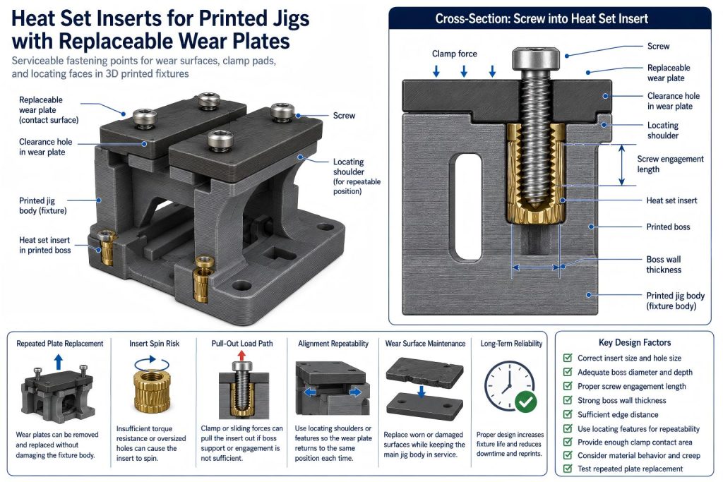
Heat set inserts for printed jigs with replaceable wear plates are used when a 3D printed fixture body needs removable contact plates, sacrificial wear strips, locating faces, guide blocks, clamp pads, or replaceable surfaces that may be changed after repeated use.
This application is different from a general printed fixture. A jig with replaceable wear plates separates the durable fixture body from the surfaces that experience wear, abrasion, compression, sliding, clamping, or repeated part contact. Heat set inserts make the wear plates removable without damaging the printed fixture body each time the plates are replaced.
For broader fixture context, see Heat Set Inserts in 3D Printed Industrial Fixtures and Heat Set Inserts in 3D Printed CNC Fixture Plates.
Why Replaceable Wear Plates Need a Specific Insert Design Approach
Printed jigs and fixtures often fail first at contact surfaces, not in the main body. A locating face may wear down, a clamp pad may deform, a sliding surface may become rough, or a guide edge may lose accuracy after repeated use.
A replaceable wear plate allows the worn surface to be changed while keeping the printed fixture body in service. This creates a different fastening problem than a permanent assembly.
The insert joint may need to handle:
- repeated plate removal and replacement
- screw tightening during maintenance
- localized clamp force
- wear plate alignment requirements
- insert torque resistance during repeated service
- pull-out loads from clamping or part handling
- boss stress near fixture edges
- material creep under sustained fixture pressure
For this reason, printed jigs with replaceable wear plates should be designed as serviceable fastening structures, not just as printed blocks with screws.
Typical Replaceable Wear Plate Use Cases
Heat set inserts may be useful in printed jigs and fixtures when a contact surface needs to be replaced, adjusted, or serviced without rebuilding the entire printed fixture.
Common examples include:
- replaceable clamp pads
- sacrificial wear strips
- locating plates
- guide surfaces
- soft jaws or printed holding blocks
- inspection fixture contact faces
- drill guide backing plates
- assembly nest wear surfaces
- sliding contact plates
- low-volume production fixture inserts
In these applications, the heat set insert becomes a service point. The goal is to replace the worn plate while preserving the main printed jig body.
Main Failure Modes in Replaceable Wear Plate Jigs
Insert Spin During Plate Replacement
If the insert does not have enough torque resistance, it may rotate when the wear plate screw is tightened or removed. This is more likely when the printed hole is too large, the insert was installed with poor plastic flow, or the screw is overtightened during maintenance.
See also: Why Do Heat Set Inserts Spin in 3D Printed Parts?
Pull-Out from Clamp Loads
A wear plate may carry clamp force, part contact force, or sliding load. If the insert is too short, the boss is weak, or the load path pulls the plate away from the fixture body, the insert may pull out of the printed structure.
See also: Pull-Out Strength of Heat Set Inserts in 3D Printed Parts.
Thread Loosening After Repeated Plate Changes
A fixture may go through repeated service cycles as wear plates are removed, replaced, shimmed, or cleaned. Repeated screw removal can reduce joint stability if the insert, boss, screw engagement, or material behavior is not designed for service.
See also: Why Do Threaded Inserts Loosen After Repeated Screw Removal?
Boss Cracking Near Fixture Edges
Wear plates are often placed near fixture edges, corners, slots, or part-contact zones. If the insert boss is too close to an edge or has thin surrounding material, the fixture body may crack during installation or repeated screw tightening.
See also: Why Do Heat Set Inserts Fail Near Edges or Corners?
Alignment Loss After Plate Replacement
A replaceable wear plate can fail functionally even if the insert remains secure. If the plate shifts after tightening, the locating surface may no longer hold the part in the correct position. The insert joint, screw clearance, washer area, and locating features must work together.
Design Variables for Replaceable Wear Plate Jigs
A reliable replaceable wear plate structure should be designed around the complete fixture system, not only around the insert size.
| Design Variable | Why It Matters in Replaceable Wear Plate Jigs |
|---|---|
| Insert size | Affects thread engagement, torque resistance, and available boss geometry. |
| Hole size | Controls insert fit, plastic flow, installation stress, and long-term retention. |
| Boss diameter | Determines how much printed material supports the insert during repeated plate service. |
| Boss depth | Helps prevent proud inserts, shallow support, and screw bottoming. |
| Screw engagement length | Controls clamp stability without bottoming out inside the insert or boss. |
| Wear plate thickness | Affects screw length, seating behavior, stiffness, and contact pressure. |
| Locating features | Help repeat plate position without relying only on screw friction. |
| Clamp force | May compress the printed body, wear plate, or local screw contact area. |
| Material behavior | PLA, PETG, ABS, nylon, and carbon fiber nylon respond differently to pressure, heat, and repeated assembly. |
For general hole design, see the Heat Set Insert Hole Size Guide. For boss geometry, see How to Design Bosses for Heat Set Inserts.
Recommended Fastening Structure
For printed jigs with replaceable wear plates, the heat set inserts are usually best installed in the main fixture body. The replaceable wear plate should use clearance holes, counterbored holes, or slots depending on the required alignment and service method.
A typical structure includes:
- a printed fixture body with heat set inserts installed in supported bosses
- a replaceable wear plate with clearance holes
- screws that clamp the wear plate to the fixture body
- enough boss diameter and depth around each insert
- controlled screw engagement length
- locating features if repeatable plate position matters
- enough contact area to prevent local plastic crushing
The screws should clamp the wear plate. They should not be the only features responsible for accurate plate location if the fixture requires repeatable positioning.
Wear Plate Alignment and Locating Features
If the wear plate defines a locating surface, screw clearance alone may not provide repeatable alignment. Clearance holes allow assembly, but they can also allow small shifts before tightening.
For better repeatability, consider adding:
- printed shoulders
- pocketed plate seats
- dowel features where appropriate
- edge stops
- flat reference faces
- controlled clearance around the plate
The insert provides reusable clamping. The locating geometry provides repeatable position. These two jobs should not be confused.
Screw Engagement and Plate Replacement
Screw engagement length should be long enough to provide stable clamping during repeated wear plate replacement, but not so long that the screw bottoms out inside the insert or below the boss.
A screw that is too short may not provide enough clamp force. A screw that is too long may create false tightening resistance, damage the insert joint, or push against the bottom of the printed cavity.
When checking screw engagement, consider:
- wear plate thickness
- washer or counterbore depth
- insert thread depth
- boss depth
- clearance below the insert
- expected number of plate replacement cycles
- whether the plate carries clamp, sliding, or impact load
For deeper reference, see Screw Engagement Length for Heat Set Inserts in 3D Printed Parts.
Torque Resistance During Maintenance
Replaceable wear plates may be removed and reinstalled many times. If the insert has poor torque resistance, the insert can spin during screw removal or tightening, making the fixture difficult to service.
Torque resistance depends on insert geometry, printed hole size, boss support, material behavior, installation temperature, and screw tightening torque. In serviceable jigs, torque resistance matters because the fastener is not installed only once.
For deeper reference, see Torque Resistance of Heat Set Inserts in 3D Printed Parts.
Material Behavior in Printed Jigs
Material choice affects fixture durability, insert retention, and wear plate stability.
PLA can be stiff and dimensionally useful for light fixtures, but it may crack around tight inserts or under impact. PETG is tougher, but it may creep under sustained clamp load. ABS can tolerate heat better than PLA, but still depends on boss design and hole fit. Nylon and carbon fiber nylon may provide better toughness for demanding fixtures, but printed tolerance, moisture behavior, and local stress concentration still matter.
For material comparison, see PLA vs PETG vs ABS for Threaded Inserts.
Repeated Assembly Design Checks
Before relying on heat set inserts in a printed jig with replaceable wear plates, check the following:
- Confirm the insert dimensions and recommended printed hole size.
- Print a test coupon using the same material and settings.
- Check that the wear plate seats flat before screw tightening.
- Confirm that screw length does not bottom out.
- Add locating features if plate position must repeat accurately.
- Check boss diameter and boss depth around each insert.
- Keep inserts away from thin edges, slots, and weak corners.
- Test several plate removal and replacement cycles.
- Inspect for insert spin after repeated tightening.
- Check whether clamp force deforms the printed fixture body.
For broader repeated fastening behavior, see Heat Set Inserts for Repeated Assembly in 3D Printed Parts.
When Heat Set Inserts Are a Good Fit
Heat set inserts are a good fit for printed jigs with replaceable wear plates when the design needs:
- serviceable wear surfaces
- repeatable plate replacement
- stronger threads than printed plastic threads
- durable clamp points
- replaceable contact pads or guide surfaces
- low-volume production fixture maintenance
- longer fixture life without reprinting the full body
They are especially useful when the printed fixture body is still usable, but the contact surface is expected to wear out first.
When the Design Needs More Caution
Heat set inserts need more caution when:
- the insert is close to a thin edge or slot
- the wear plate carries high clamp load
- the fixture body is thin below the insert
- the wear plate must locate with high precision
- the screw may be removed very frequently
- the fixture material may creep under sustained load
- the plate is used as a high-force structural clamp surface
If the broader fixture structure is the main design question, see Heat Set Inserts in 3D Printed Industrial Fixtures.
Practical Summary
Heat set inserts for printed jigs with replaceable wear plates should be designed as serviceable fastening points. The insert, boss, screw, wear plate, locating features, printed material, clamp force, and replacement cycle all affect long-term reliability.
A good replaceable wear plate design should allow the worn surface to be changed without damaging the main printed jig body, spinning the insert, cracking the boss, or losing alignment after replacement.
For printed jigs, the key question is not only whether the insert holds the plate once. The more important question is whether the fixture remains usable after repeated wear, service, and plate replacement.
FAQ
Are heat set inserts useful for printed jigs with replaceable wear plates?
Yes. Heat set inserts are useful when a printed jig needs removable wear plates, clamp pads, guide surfaces, or locating faces that may be replaced after repeated use.
Should the insert be installed in the wear plate or the fixture body?
In most designs, the insert should be installed in the main printed fixture body. The replaceable wear plate should usually use clearance holes so it can be removed and replaced.
Why do inserts spin during wear plate replacement?
Inserts can spin if the printed hole is too large, the boss is weak, the insert has poor knurl engagement, or the screw tightening torque exceeds the insert joint’s torque resistance.
Do replaceable wear plates need locating features?
If repeatable position matters, yes. Screws provide clamp force, but locating features help control plate position. A fixture should not rely only on screw clearance holes for accurate repeatability.
Can PETG be used for printed jigs with replaceable wear plates?
PETG can be used for some fixture applications, but it may creep under sustained clamp force. If the wear plate is heavily loaded, material behavior should be tested before production use.
Should wear plate replacement be tested before using the jig?
Yes. Repeated plate removal and reinstallation can reveal insert spin, boss cracking, screw bottoming, clamp loss, and alignment drift before the jig is used in production or repeated assembly work.
Related Guides
- Heat Set Inserts in 3D Printed Industrial Fixtures
- Heat Set Inserts in 3D Printed CNC Fixture Plates
- Heat Set Inserts for Repeated Assembly in 3D Printed Parts
- Heat Set Insert Hole Size Guide
- How to Design Bosses for Heat Set Inserts
- Pull-Out Strength of Heat Set Inserts in 3D Printed Parts
- Torque Resistance of Heat Set Inserts in 3D Printed Parts
- Why Do Threaded Inserts Loosen After Repeated Screw Removal?
Related Decision Resources
For insert selection, tool choice, and supplier comparison, use these decision-focused references after the engineering requirements are defined.