
Industrial fixtures are used to hold, locate, clamp, align, or support parts during manufacturing, assembly, inspection, testing, and small-batch production. Unlike decorative prints or simple brackets, fixtures are working tools. They are handled repeatedly, tightened repeatedly, adjusted repeatedly, and sometimes loaded in the same direction hundreds or thousands of times.
For 3D printed industrial fixtures, heat set inserts are useful because they create durable metal threads inside printed plastic. They allow clamps, stops, locating blocks, replaceable plates, and adjustment hardware to be fastened securely without wearing out the printed hole.
But an insert alone does not make a fixture reliable.
In fixture applications, the insert must work as part of a larger mechanical system. The screw, clamp, insert, boss, printed body, ribs, and fixture base all carry load together. If the insert is placed in a thin wall, unsupported boss, weak layer direction, or high-stress clamping zone, the fixture may fail even if the insert itself is properly installed.
The key point is:
A 3D printed industrial fixture should treat each heat set insert as a load-transfer point, not just a threaded hole.
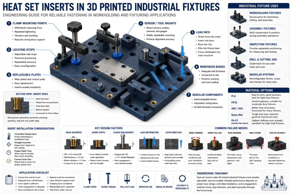
Why Industrial Fixtures Use Heat Set Inserts
Industrial fixtures often need threaded connections that survive repeated use. A fixture may be assembled once, adjusted many times, or used every day on a workbench, production line, inspection station, or machine setup.
Common fixture functions include:
- holding a workpiece in position
- clamping a part during assembly
- locating a component with repeatable accuracy
- supporting test equipment
- securing replaceable wear plates
- mounting sensors or inspection tools
- positioning small production parts
- holding drill guides or cutting templates
- creating modular workholding systems
Printed plastic threads can work for light-duty prototypes, but they usually become unreliable when screws are tightened and removed repeatedly. Heat set inserts improve thread durability and make the fixture more serviceable.
This is especially important when the fixture includes:
- removable clamps
- adjustable stops
- repeated screw tightening
- replaceable contact surfaces
- metal hardware attached to plastic
- modular components that need reconfiguration
In these applications, the insert is not just a convenience. It is part of the fixture’s working structure.
Common Insert Locations in 3D Printed Fixtures
Heat set inserts are usually placed where a screw connection needs to remain stable after repeated use.
Clamp Mounting Points
Clamp mounting points are one of the most demanding insert locations in a fixture. A clamp screw may apply direct pressure to a workpiece, hold a component against a stop, or secure a movable jaw.
The insert area must resist:
- clamping force
- screw torque
- repeated tightening
- vibration from handling or machining(For clamp screws that are tightened repeatedly by hand tools, torque resistance helps prevent the insert from rotating inside the printed boss.)
- local bending around the clamp base
- long-term deformation of the printed material
If the insert is placed in a thin printed wall, the fixture may crack or deform when the clamp is tightened. If the boss is unsupported, the insert may pull upward or rotate inside the plastic.
Clamp inserts should be supported by thick boss geometry, ribs, or a reinforced fixture base.
Adjustable Stops and Locating Blocks
Many fixtures use adjustable stops, side blocks, or locating pins to position a part consistently. These components may not carry the same load as clamps, but they require repeatable alignment.
Heat set inserts help when the stop needs to be moved, replaced, or locked in place with screws.
For locating features, insert placement should avoid distortion. If the insert installation deforms the fixture surface, the stop may no longer sit flat or square.
Replaceable Wear Plates
Fixtures sometimes include replaceable plates or contact pads where the workpiece touches the tool. These areas may wear over time, especially if parts are loaded and removed repeatedly.
Heat set inserts allow wear plates to be replaced without damaging the printed fixture body.
The insert should be placed in a stable region with enough surrounding material so that plate replacement does not loosen the threaded connection over time.
Sensor and Inspection Mounts
Inspection fixtures may hold sensors, probes, cameras, switches, or measurement references. These inserts often carry lighter loads, but alignment is critical.
The boss around the insert should remain dimensionally stable. Overheated installation, thin walls, or flexible geometry can shift the mounting point and reduce inspection accuracy.
Modular Fixture Connections
Some 3D printed fixtures are built as modular systems, where blocks, rails, stops, and clamps are rearranged for different jobs.
In this type of fixture, inserts may experience frequent screw cycling. Thread durability and insert retention become more important than maximum strength alone.
Clamping Force and Insert Load Paths
Industrial fixtures often fail when designers underestimate clamping force.
A screw does not only hold a component in place. When tightened, it creates a clamping load that travels through the screw head, into the attached clamp or block, through the insert, into the boss, and finally into the fixture body.
In clamping fixtures, pull-out strength should be evaluated as part of the full load path from the screw and clamp into the printed fixture body.
This load path matters.
If the insert is isolated in a small boss, the force concentrates around that boss. The fixture may crack, flex, or allow the insert to spin. If the boss is connected to ribs, walls, or a thick base plate, the load spreads into the larger fixture structure.
A strong fixture insert design should consider:
- where the screw force enters the fixture
- whether the boss is connected to the base
- whether ribs support the clamping direction
- whether the insert is loaded in tension, shear, or torque
- whether the fixture body flexes under tightening
- whether the workpiece load pushes back into the clamp
For clamping applications, the insert should not be treated as a small local feature. It is a structural node in the fixture.
Boss Design for Fixture Inserts
The boss around the insert is one of the most important parts of a 3D printed industrial fixture.
A good boss provides enough material to resist cracking, spinning, pull-out, and long-term deformation. This is especially important because fixtures are often tightened by hand tools, and users may apply more torque than expected.
Important boss design factors include:
- outer boss diameter
- wall thickness around the insert
- insert depth
- bottom material thickness
- distance from edges
- connection to ribs or fixture walls
- support under the clamp direction
- screw engagement length
- clearance for the mating part
A fixture boss should not be a thin cylinder sitting on top of a flat plate. That type of geometry may look clean in CAD, but it often performs poorly under clamping loads.
A stronger design connects the insert boss to the main fixture body with ribs, gussets, or thickened regions. This helps transfer load from the insert into the base.
For high-use fixtures, it is better to slightly increase material around critical inserts than to save a few grams and risk fixture failure.
Insert Depth and Screw Engagement
Insert depth and screw engagement length determine how much of the threaded connection is actually doing work.
If the insert is too shallow, it may pull out under clamping or adjustment loads. If the screw engagement is too short, the screw may loosen, strip, or fail to create consistent clamping force.
If the screw is too long, it may bottom out below the insert and apply stress to the plastic instead of clamping the attached component properly.
For fixture applications, screw engagement should be matched to:
- screw size
- insert length
- expected clamp force
- number of assembly cycles
- material stiffness
- boss depth
- part thickness being clamped
- whether the screw is frequently removed
A fixture used once may tolerate a weaker connection. A fixture used daily needs a more durable one.
Repeated tightening is a quiet little stress accountant. It keeps a ledger in the plastic. Poor engagement pays interest.
Material Choice for Printed Industrial Fixtures
The material used for the fixture affects insert performance.
PLA
PLA is easy to print and dimensionally stable, which can make it useful for light-duty fixtures, inspection templates, and low-load positioning tools.
However, PLA can be brittle and may soften near heat. It is not ideal for fixtures that experience high clamping force, impact, elevated temperature, or repeated heavy tightening.
PLA fixtures with heat set inserts should use generous boss geometry and avoid thin unsupported insert walls.
PETG
PETG offers better toughness than PLA and can work well for moderate-duty fixtures. It is less brittle, but it can flex more under load.
In PETG fixtures, insert bosses should be designed to prevent creep or deformation under sustained clamping force.
PETG can be suitable for assembly aids, light workholding, covers, and adjustable positioning tools.
ABS and ASA
ABS and ASA offer better heat resistance than PLA and may be suitable for functional fixtures exposed to warmer environments or repeated handling.
These materials require good print quality and layer adhesion. Poorly printed ABS or ASA can still split around inserts or warp enough to affect fixture accuracy.
Nylon and Carbon Fiber Nylon
Nylon and carbon fiber nylon are strong candidates for industrial fixtures that require toughness, wear resistance, and functional strength.
Carbon fiber nylon can provide better stiffness and dimensional stability, especially for brackets, fixture plates, and load-bearing tooling. However, insert installation must be controlled carefully, and boss geometry still matters.
A strong material does not eliminate the need for a strong load path.
Layer Direction and Fixture Reliability
Layer direction is critical in 3D printed fixtures because the insert load may act across weak printed layers.
For fixture plates and clamp bosses, layer adhesion and insert strength should be considered together because repeated tightening may load the insert across printed layer lines.
A fixture insert can fail by pulling layers apart if:
- the screw load pulls upward across layer lines
- the clamp bends the fixture base
- the boss is printed in a weak orientation
- the insert expands the boss during installation
- ribs do not support the load direction
- the fixture is repeatedly tightened in the same region
For fixture plates, print orientation should be chosen so that the insert boss and surrounding structure resist the real clamping direction.
If the insert will be pulled upward, the surrounding layers must resist pull-out. If the insert will resist rotation, the boss and nearby ribs must resist torque. If the fixture body will bend, the insert should not be placed in an unsupported flexible zone.
Layer orientation is not only a print setting. It is part of the fastening design.
Replaceable Components and Serviceability
One advantage of using heat set inserts in 3D printed fixtures is serviceability.
Fixtures often evolve. A stop may need to move. A clamp may need to be replaced. A wear surface may need a new plate. A sensor bracket may need adjustment. A production part may change slightly, requiring a modified contact block.
Heat set inserts make this kind of modification easier because the printed fixture body can remain in use while attached hardware is removed or replaced.
Useful serviceable fixture features include:
- replaceable clamp pads
- adjustable side stops
- removable locator blocks
- replaceable drill bushings or guide plates
- interchangeable sensor mounts
- modular fixture blocks
- removable covers or guards
In these cases, insert reliability is not only about maximum load. It is also about surviving repeated assembly cycles without thread wear.
Common Failure Modes in Fixture Inserts
Heat set inserts in 3D printed industrial fixtures tend to fail in predictable ways.
Insert Spinning
Insert spinning happens when the insert rotates inside the printed part as the screw is tightened or removed.
Common causes include:
- oversized hole
- poor heat insertion
- insufficient boss wall thickness
- excessive screw torque
- weak material around the insert
- lack of anti-rotation support in the boss
In fixtures, insert spinning is common when users tighten clamps aggressively.
Insert Pull-Out
Insert pull-out occurs when the insert is pulled out of the fixture body under tension.
This may happen when:
- clamp load pulls upward on the insert
- the boss is too shallow
- insert depth is insufficient
- the boss is not connected to the base
- bottom material is too thin
- layer direction is weak
- the fixture is used beyond its intended load
Pull-out is especially important in clamp mounts and replaceable plate fasteners.
Boss Cracking
Boss cracking can happen during installation or during use.
Typical causes include:
- hole too small
- insert installed too cold and forced into place
- insert installed too hot and damaging the material(For high-use fixtures, installation temperature should be controlled carefully so the insert seats cleanly without cracking or weakening the boss.)
- thin boss walls
- insert too close to an edge
- brittle material
- sharp geometry around the boss
Boss cracking may appear immediately, or it may grow after repeated tightening.
Fixture Base Flexing
Sometimes the insert does not fail directly. Instead, the printed base flexes around it.
This can reduce clamping accuracy and repeatability. A fixture may still “work,” but the part being held may shift slightly under load.
Base flexing is often caused by:
- thin fixture plates
- lack of ribs
- clamps placed too far from support
- insert bosses not tied into the base
- flexible material choice
Loss of Accuracy
Industrial fixtures are often used because they hold parts in a repeatable position. If insert installation distorts the fixture, or if repeated screw tightening deforms the mounting area, the fixture may lose accuracy.
This is especially important for inspection fixtures, drilling guides, sensor mounts, and assembly alignment tools.
Design Checklist for Heat Set Inserts in Industrial Fixtures
Before using heat set inserts in a 3D printed industrial fixture, check the following:
- Is the insert located in a real load-bearing or serviceable area?
- Does the boss have enough wall thickness?
- Is there enough material below the insert?
- Is the insert far enough from edges and thin walls?
- Is the boss connected to ribs, gussets, or the fixture base?
- Is the screw engagement length sufficient?
- Will the screw be tightened repeatedly?
- Will the insert carry clamp force, pull-out load, or torque?
- Does the fixture base flex under clamping?
- Is the material suitable for repeated use?
- Does the print orientation support the load direction?
- Could installation heat distort an accuracy-critical feature?
- Are replaceable components supported by durable threaded connections?
- Has the fixture been tested under real tightening and workholding conditions?
A fixture insert should be designed for the way the tool will actually be used, not only for how it appears in CAD.
Engineering Takeaway
Heat set inserts can make 3D printed industrial fixtures more durable, adjustable, and serviceable. They are especially useful for clamps, stops, replaceable plates, modular blocks, sensor mounts, and repeated-use fastening points.
But fixture reliability depends on more than the insert.
A reliable insert connection requires:
- proper hole size
- controlled installation
- sufficient boss geometry
- enough screw engagement
- support from ribs or the fixture base
- suitable material choice
- correct layer orientation
- a clear load path through the tool
Industrial fixtures are not static models. They are working tools that see repeated tightening, handling, clamping, adjustment, and wear.
For this reason, each insert should be designed as part of the fixture’s mechanical structure.
The best 3D printed fixture is not simply the one that accepts screws.
It is the one that keeps holding, locating, and clamping accurately after real use begins.
Related Failure Question
3D printed fixtures expose insert joints to clamping loads, repeated setup cycles, pull-out forces, and torque demand. For failure diagnosis, see why heat set inserts fail in 3D printed fixtures.
FAQ
Are heat set inserts useful in 3D printed industrial fixtures?
Yes. Heat set inserts are useful in 3D printed industrial fixtures because they provide durable metal threads for clamps, stops, replaceable plates, sensor mounts, and modular fixture components. They are especially helpful when screws are tightened or removed repeatedly.
Where should heat set inserts be used in a printed fixture?
Heat set inserts should be used in clamp mounting points, adjustable stops, locating blocks, replaceable wear plates, modular fixture connections, and sensor or inspection mounts where reusable threads or stronger fastening points are needed.
What causes inserts to fail in industrial fixtures?
Common causes include thin boss walls, oversized or undersized holes, poor installation temperature, insufficient insert depth, short screw engagement, weak layer orientation, unsupported bosses, excessive clamping force, and repeated overtightening.
Do fixture inserts need stronger bosses than normal printed parts?
Often, yes. Fixture inserts may carry clamping force, torque, repeated screw cycling, or alignment loads. Bosses should usually be connected to ribs, gussets, thick walls, or the fixture base to spread load into the structure.
What material is best for 3D printed fixtures with heat set inserts?
The best material depends on the load and environment. PLA can work for light-duty fixtures, PETG for moderate use, ABS or ASA for better heat resistance, and nylon or carbon fiber nylon for stronger functional fixtures. Material choice must still be paired with good boss design and print orientation.
Related Engineering Guides
- How to Choose Heat Set Inserts for 3D Printed Parts
- Heat Set Insert Hole Size Guide
- How to Design Bosses for Heat Set Inserts
- PLA vs PETG vs ABS for Threaded Inserts
- Why Heat Set Inserts Fail in 3D Printed Parts
- Pull-Out Strength of Heat Set Inserts in 3D Printed Parts
- Torque Resistance of Heat Set Inserts in 3D Printed Parts
- Layer Adhesion and Heat Set Insert Strength in 3D Printed Parts
- Heat Set Insert Installation Temperature for 3D Printed Parts
- Screw Engagement Length for Heat Set Inserts in 3D Printed Parts