
Heat set inserts in carbon fiber nylon parts are used when a 3D printed component needs durable metal threads inside a stronger functional material. Carbon fiber nylon, often referred to as PA-CF, is commonly used for brackets, mounts, fixtures, machine adapters, sensor supports, and high-load printed assemblies.
But carbon fiber nylon does not automatically solve every fastening problem.
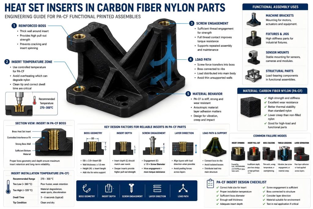
When heat set inserts are used in PA-CF printed parts, the insert still depends on the local structure around it. Boss geometry, hole size, insert depth, installation temperature, screw engagement, layer direction, and load path all affect whether the threaded connection remains reliable.
The key point is:
Carbon fiber nylon can make printed parts stronger and stiffer, but heat set insert reliability still depends on local boss design and controlled installation.
A strong material cannot compensate for a weak insert boss.
Why Carbon Fiber Nylon Is Used for Functional Printed Parts
Carbon fiber nylon is commonly selected for functional printed components because it combines nylon’s toughness with the added stiffness of chopped carbon fiber reinforcement.
It is often used for:
- machine brackets
- sensor mounts
- actuator mounts
- robotics parts
- drone and RC components
- assembly fixtures
- equipment adapters
- jigs and positioning blocks
- lightweight structural supports
- high-load printed parts
Compared with standard PLA or PETG, carbon fiber nylon can offer better stiffness, better heat resistance, improved dimensional stability, and better performance in demanding assemblies.
This makes it attractive for parts that need to hold screws, resist vibration, support load, or remain stable after repeated use.
However, the same stiffness that makes PA-CF useful can also make insert design less forgiving. If the boss wall is too thin, the hole is too small, or the insert is installed with too much heat or pressure, cracking and local damage can still occur.
PA-CF is a stronger material choice, not an excuse to ignore fastening structure.
How Heat Set Inserts Behave in PA-CF Parts
Heat set inserts work by using heat to soften the plastic around the insert. As the insert is pressed into the hole, the surrounding material flows around the insert’s knurls or outer features. After cooling, the plastic locks the insert in place.
In carbon fiber nylon, this process needs more control than in easier materials.
The designer must consider:
- whether the material softens evenly
- whether the insert temperature is appropriate
- whether the hole allows controlled plastic flow
- whether the boss has enough wall thickness
- whether the insert is pressed straight
- whether the bottom of the boss supports the insert
- whether the surrounding structure can carry the screw load
A properly installed insert in a well-designed PA-CF boss can create a strong, reusable threaded connection. But if the insert is overheated, forced into an undersized hole, or placed in a thin unsupported boss, the connection may fail even though the material itself is strong.
The insert is not only a metal thread. It is a local mechanical interface between screw force and printed structure.
Common Insert Locations in Carbon Fiber Nylon Parts
Heat set inserts are most useful in PA-CF parts where the screw joint must be repeatable, strong, or serviceable.
Common locations include:
Mounting Brackets
Functional brackets often use inserts where the part connects to a machine frame, rail, motor, sensor, or enclosure. These inserts may carry clamping force, vibration, and occasional shock loads.
The boss should be connected to the bracket body with enough material or ribs so the load does not concentrate in a small isolated cylinder.
Fixtures and Jigs
Jigs and fixtures often need threaded points for clamps, stops, locating pins, replaceable plates, or adjustable components. Heat set inserts make these printed tools more durable, especially when screws are adjusted repeatedly.
For fixtures, screw engagement and insert retention are important because users may overtighten screws during setup.
Sensor and Electronics Mounts
PA-CF is often used for sensor mounts, camera brackets, robotics modules, and electronics supports. These parts may not always carry high loads, but they require stability and repeatable assembly.
The insert should not distort the mounting surface during installation. Overheating or uneven insertion can cause misalignment.
Machine Adapters and Equipment Parts
Carbon fiber nylon is useful for adapters that connect printed parts to metal hardware. Inserts may be used where screws fasten the printed adapter to aluminum extrusion, steel brackets, motors, hinges, or covers.
In these cases, the load path from screw to insert to boss to main body should be clear and supported.
Insert Installation Temperature and Material Response
Installation temperature is one of the most important factors when using heat set inserts in carbon fiber nylon.
For PA-CF printed parts, installation temperature should be controlled together with dwell time so the material flows around the insert without damaging the boss.
If the insert is too cold, the plastic may not flow properly around the insert. The insert may require excessive force, which can crack the boss or damage the hole.
If the insert is too hot, the nylon around the hole may degrade, become weak, discolor, or lose local strength. Overheating may also enlarge the hole, reducing insert retention.
For PA-CF parts, the goal is not simply to melt the insert into place. The goal is controlled plastic flow.
A good installation process should produce:
- straight insert alignment
- complete seating
- no visible boss cracking
- no excessive melted material
- no tilted insert
- no collapsed boss wall
- no insert protruding above the surface
- no weak or burned-looking material around the hole
Dwell time matters as much as temperature. Holding the heated tip on the insert for too long can damage the surrounding material even if the set temperature appears reasonable.
For functional parts, test insert installation on a printed sample before using the final bracket or assembly component.
Boss Design for Carbon Fiber Nylon Parts
The boss is the structure that allows the insert to work.
A heat set insert should not be placed in a thin wall without surrounding support. The boss must provide enough plastic around the insert to resist cracking, spinning, pull-out, and deformation.
Important boss design factors include:
- outer boss diameter
- wall thickness around the insert
- insert depth
- bottom material thickness
- distance from edges
- support ribs
- connection to the main bracket body
- load direction
- print orientation
A common mistake is assuming that carbon fiber nylon is strong enough to use very thin insert walls. In reality, thin boss walls can still crack during installation or screw tightening.
For high-load brackets, the boss should not stand alone. It should be connected to ribs, walls, gussets, or thicker structural zones. This helps transfer screw force into the main part instead of concentrating it around the insert.
In other words:
The insert boss should be part of the structure, not a small tower added to the surface.
Screw Engagement and Load Transfer
Screw engagement length affects how the threaded connection carries load.
If the screw only engages a small portion of the insert, the joint may loosen or strip under vibration, repeated tightening, or load cycling. If the screw is too long, it may bottom out, push against the boss, or create unintended stress.
For PA-CF parts, screw engagement should be matched to:
- insert length
- screw size
- expected load
- number of assembly cycles
- vibration level
- clamping requirement
- available boss depth
A good insert connection allows the screw to engage enough thread without bottoming out or overloading the plastic below the insert.
The load path matters too. When a screw is tightened, the force does not stop at the insert. It travels from the screw head into the mating component, through the insert, into the boss, and then into the printed part.
If the boss is connected to a reinforced rib or thick bracket wall, the load can spread more effectively. If the boss is isolated on a thin plate, the area around the insert may flex, crack, or deform.
Layer Direction and Reinforced Nylon Behavior
Carbon fiber nylon parts are still 3D printed parts. They are not equally strong in every direction.
Layer orientation affects insert performance because pull-out, torque, and clamping loads may act across printed layer lines. For reinforced nylon parts, layer adhesion and insert strength should be evaluated together because carbon fiber reinforcement does not remove the anisotropy of the printed structure. Even with carbon fiber reinforcement, weak layer adhesion or poor print orientation can reduce insert reliability.
Important questions include:
- Does the screw load pull across layer lines?
- Is the boss built in a direction that resists cracking?
- Does the insert push layers apart during installation?
- Are ribs printed in a useful orientation?
- Will the bracket experience bending or vibration across the layer direction?
Carbon fiber filled filaments may improve stiffness, but they can also make printed parts more anisotropic. The part may be strong along certain directions and weaker across layer boundaries.
This is why insert placement should be considered together with print orientation.
A well-designed PA-CF insert boss should account for both geometry and layer behavior.
Common Failure Modes in PA-CF Insert Applications
Heat set inserts in carbon fiber nylon parts can fail in several predictable ways.
Insert Spinning
Insert spinning happens when the insert rotates inside the plastic during screw tightening or removal.
Common causes include:
- oversized hole
- overheated installation
- insufficient boss wall thickness
- poor plastic flow around the insert
- excessive screw torque
- weak local geometry
A spinning insert is often a sign that the material around the insert did not mechanically lock the insert properly.
Insert Pull-Out
Insert pull-out happens when the insert is pulled out of the part under tension.
This can occur when:
- the insert is too shallow
- the boss is too short
- the bottom material is too thin
- the screw load is too high
- the insert is placed in a weak local section
- the boss is not connected to the main load-bearing body
Pull-out resistance depends heavily on insert depth, boss geometry, and material support below and around the insert.
Boss Cracking
Boss cracking can occur during insert installation or screw tightening.
Typical causes include:
- hole too small
- insert pressed in too aggressively
- temperature too low, requiring excessive force
- temperature too high, damaging local material
- boss wall too thin
- insert too close to the edge
- sharp transitions around the boss
Even in carbon fiber nylon, the insert zone needs enough material to absorb installation stress.
Thread Loosening
Thread loosening may occur when the assembly experiences vibration, repeated motion, or inconsistent clamping.
Causes may include:
- short screw engagement
- insufficient preload
- flexible surrounding structure
- local creep
- poor boss support
- vibration transmitted through the part
PA-CF can improve stiffness, but the screw joint still needs proper engagement and support.
Layer Separation
Layer separation happens when the printed layers split around the insert, boss, or bracket body.
This may result from:
- poor print orientation
- weak layer bonding
- high pull-out load
- bending load near the insert
- insert installed across a weak layer direction
- unsupported boss geometry
This is a structural issue, not only an insert issue.
Design Checklist for PA-CF Insert Applications
Before using heat set inserts in carbon fiber nylon printed parts, check the following:
- Is the insert placed in a true load-bearing zone?
- Does the boss have enough outer diameter?
- Is the wall around the insert thick enough?
- Is there enough material below the insert?
- Is the hole size matched to the insert?
- Is the insert depth appropriate for the screw?
- Is the screw engagement length sufficient?
- Is the boss connected to ribs or the main bracket body?
- Is the insert far enough from edges and thin walls?
- Is the installation temperature controlled?
- Is dwell time controlled during insertion?
- Is the insert pressed straight into the hole?
- Does the print orientation support the load direction?
- Will the part experience vibration, impact, or repeated service?
- Has the insert design been tested in a real application?
For low-load covers, the design can be lighter. For brackets, fixtures, machine mounts, and structural parts, the boss and load path need more attention.
Not every insert location in a PA-CF part should use the same geometry.
Engineering Takeaway
Carbon fiber nylon is a strong candidate for functional 3D printed parts, especially when the part must carry load, resist wear, hold alignment, or survive repeated use.
But heat set inserts in PA-CF parts are only reliable when the surrounding structure is designed correctly.
A strong insert application depends on:
- correct hole size
- controlled installation temperature
- sufficient boss wall thickness
- proper insert depth
- enough screw engagement
- good layer orientation
- reinforced load paths
- real support from the bracket body
Carbon fiber nylon improves the material foundation, but the insert still lives or dies in the local geometry.
For functional printed parts, the best design is not simply “use PA-CF and add inserts.”
The better approach is:
Use PA-CF where the material helps, then design each insert boss as a supported load-transfer structure.
FAQ
Can you use heat set inserts in carbon fiber nylon parts?
Yes. Heat set inserts can be used in carbon fiber nylon parts, especially for brackets, mounts, fixtures, and functional assemblies that require reusable metal threads. The insert area must be designed with proper boss geometry, hole size, installation temperature, and screw engagement.
Is carbon fiber nylon stronger than PLA or PETG for threaded inserts?
Carbon fiber nylon is usually stiffer and more suitable for functional parts than PLA or PETG, but insert strength still depends on local design. A poorly designed boss in PA-CF can still crack, loosen, or fail.
What causes inserts to fail in PA-CF printed parts?
Common causes include oversized holes, overheated installation, thin boss walls, insufficient insert depth, short screw engagement, poor layer orientation, and unsupported load paths.
Do carbon fiber nylon parts need different insert installation settings?
Yes. PA-CF materials often require more controlled installation than standard PLA or PETG. Temperature, dwell time, hole size, and insertion pressure should be tested on sample parts before final assembly.
Should insert bosses in PA-CF parts be reinforced?
Yes. For functional brackets and high-load parts, insert bosses should connect to ribs, gussets, thick walls, or the main body of the part. Isolated bosses are more likely to crack, spin, or pull out under load.
Related Engineering Guides
- How to Choose Heat Set Inserts for 3D Printed Parts
- Heat Set Insert Hole Size Guide
- How to Design Bosses for Heat Set Inserts
- PLA vs PETG vs ABS for Threaded Inserts
- Why Heat Set Inserts Fail in 3D Printed Parts
- Pull-Out Strength of Heat Set Inserts in 3D Printed Parts
- Torque Resistance of Heat Set Inserts in 3D Printed Parts
- Layer Adhesion and Heat Set Insert Strength in 3D Printed Parts
- Heat Set Insert Installation Temperature for 3D Printed Parts
- Screw Engagement Length for Heat Set Inserts in 3D Printed Parts
Related Decision Resources
For insert selection, tool choice, and supplier comparison, use these decision-focused references after the engineering requirements are defined.