
Drone frames are lightweight structures, but their fastening points often carry concentrated mechanical loads. A motor mount screw, battery tray screw, flight controller stack screw, or removable cover screw may look small, but each one transfers vibration, clamping force, impact, and repeated assembly stress into the printed structure.
For 3D printed drone frames, heat set inserts are useful because they provide durable metal threads inside plastic parts. They allow screws to be removed and reinstalled many times without damaging the printed hole. However, an insert alone does not make a drone frame reliable.
In drone assemblies, insert performance depends on the full fastening structure around it: material choice, boss geometry, wall thickness, layer direction, screw engagement length, and the type of load applied during flight.
The key point is simple:
A drone frame should not treat threaded inserts as isolated metal parts. Each insert must be designed as part of a lightweight load-bearing structure.
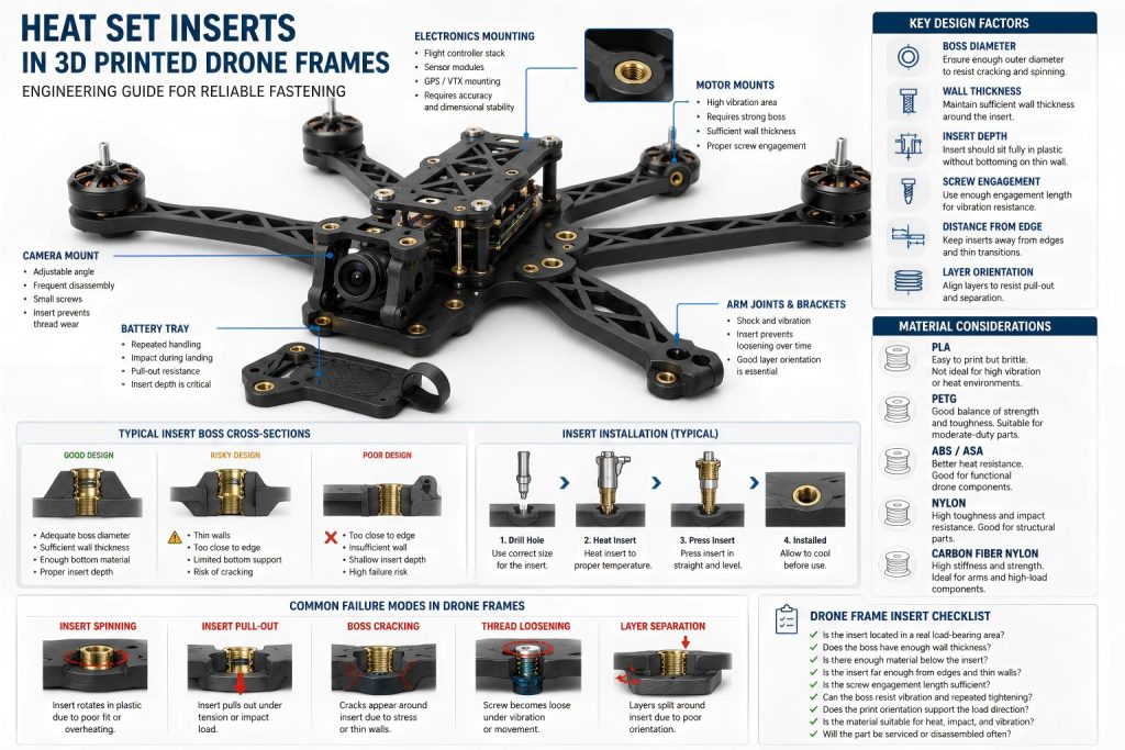
Why Drone Frames Need Reliable Threaded Inserts
Drone frames often combine low weight with repeated mechanical stress. Unlike static printed brackets, drone parts are exposed to vibration from motors, impact during landing, screw tightening during maintenance, and frequent removal of batteries, covers, and electronic modules.
Common fastening areas include:
- motor mounts
- arm joints
- battery trays
- flight controller stacks
- sensor brackets
- electronics covers
- protective shells
- modular camera mounts
In these areas, a simple printed thread may wear out quickly, especially in softer or lower-temperature materials. Heat set inserts create stronger, reusable threads, but only if the surrounding plastic can support the insert under load.
For drone frames, the main design challenge is not only thread strength. It is the balance between:
- lightweight structure
- vibration resistance
- insert retention
- boss strength
- crash tolerance
- serviceability
A drone frame that is too light may crack around the inserts. A frame that is too bulky may become heavy and inefficient. Good insert design sits between these two extremes.
Common Insert Locations in 3D Printed Drone Frames
Heat set inserts are usually placed in locations where screws must be removed, tightened, or adjusted repeatedly.
Motor Mount Inserts
Motor mounts are one of the most demanding insert locations. The screws hold the motor to the arm or frame plate, and the insert area must resist vibration, torque, and repeated screw tightening.
If the insert is placed too close to a thin wall, the boss may crack. If the hole is too large, the insert may pull out or spin. If the screw engagement is too short, the connection may loosen under vibration.
Motor mount inserts need enough surrounding plastic to distribute the load from the screw head into the printed arm.
Battery Tray Inserts
Battery trays experience repeated handling. The screws may hold straps, clamps, covers, or removable trays. These inserts usually do not experience the same direct motor vibration as motor mounts, but they often face repeated service loads.
The insert area should resist pull-out and should not be placed in very thin bottom walls. If the battery is heavy, the tray inserts may experience shock loads during landing or sudden movement.
Flight Controller Stack Inserts
Flight controller stacks often use small screws and spacers. These connections are usually lighter than motor mounts, but they require dimensional stability and repeatable assembly.
The insert must be placed accurately so that the stack remains aligned. Overheating the insert during installation can deform the mounting point and affect board alignment.
Cover and Sensor Bracket Inserts
Removable covers, sensor brackets, camera mounts, and antenna supports benefit from heat set inserts because they may be opened or adjusted many times.
These inserts often fail not from large loads, but from repeated screw removal, overtightening, or thin local geometry.
Motor Mount Inserts and Vibration Loads
Motor mount areas deserve special attention because motors produce continuous vibration during operation. For motor mount regions exposed to repeated tightening and vibration, torque resistance helps prevent inserts from rotating inside the printed boss. Even when the drone appears stable, the motor screws and insert locations are exposed to repeated micro-movement.
The insert must resist:
- screw loosening
- insert rotation
- local plastic creep
- boss cracking
- layer separation around the arm
- fatigue around the screw hole
A common design mistake is placing inserts directly into a thin printed arm without enough boss structure. The insert may install cleanly, but the surrounding plastic may not have enough cross-section to carry vibration loads.
For motor mount regions, the design should include:
- sufficient boss diameter
- adequate wall thickness around the insert
- enough material below the insert
- controlled insert depth
- proper screw engagement length
- layer direction that does not split under clamping force
The motor mount should be treated as a load path, not just a screw location. The force moves from the screw head into the insert, then into the boss, then into the arm or frame plate.
Battery Tray and Cover Fastening
Battery trays and removable covers usually fail in a different way. Instead of constant high-frequency vibration, they often experience repeated handling, screw cycling, and impact-related loads.
A battery tray insert may fail if:
- the insert is installed too close to the edge
- the tray wall is too thin
- the screw is overtightened
- the plastic softens near heat sources
- the battery mass creates shock loads during landing
For removable covers, the most common problem is thread wear or insert loosening after repeated maintenance. This is exactly where heat set inserts are useful, but the surrounding geometry still matters.
Small cover screws should not be driven into oversized inserts or shallow bosses. A small screw with poor engagement can loosen easily, especially when the frame vibrates.
In battery trays, covers, and crash-loaded brackets, pull-out strength depends on insert depth, boss support, and the amount of material surrounding the insert.
Flight Controller and Electronics Mounting
Electronics mounting points require a different kind of reliability. The load may be lower, but accuracy matters more.
For flight controller stacks, sensor boards, GPS brackets, and camera mounts, the insert must maintain alignment. If the insert shifts during installation, the board may sit unevenly or the screw pattern may no longer match.
Important design considerations include:
- avoid overheating the insert
- keep the boss top surface flat
- allow enough material under the insert
- avoid placing inserts in thin flexible tabs
- use consistent screw sizes across the electronics stack
- avoid excessive tightening on small boards
For electronics areas, insert design should support repeatable assembly without distorting the printed frame.
Material Considerations for Drone Frame Inserts
Material choice strongly affects insert performance in drone frames.
PLA
PLA is stiff and easy to print, but it can soften at relatively low temperatures and may crack under impact. It may work for prototypes, light-duty frames, fixtures, or non-critical covers, but it is not usually the best choice for high-vibration or heat-exposed drone structures.
PLA insert areas should avoid high motor heat, repeated impact, and thin brittle bosses.
PETG
PETG is tougher than PLA and offers better impact resistance, but it can be more flexible. Insert bosses in PETG should be designed with enough wall thickness to prevent deformation or creep under screw clamping.
PETG can work for moderate-duty drone parts, especially battery trays, covers, and electronics brackets.
ABS / ASA
ABS and ASA offer better heat resistance than PLA and can be useful for more demanding drone parts. They may handle heat and vibration better, but print quality, layer adhesion, and dimensional control become important.
These materials can be suitable for functional drone frame components if the insert holes and bosses are well designed.
Nylon and Carbon Fiber Nylon
Nylon and carbon fiber filled nylon are often used for stronger functional parts. Carbon fiber nylon can provide stiffness and improved dimensional stability, but insert installation must be controlled carefully because filled materials can behave differently during heat insertion.
For drone frames that need higher durability, carbon fiber nylon is often a strong candidate, especially for arms, brackets, and structural mounting regions.
Boss Design and Layer Direction
The insert is only as reliable as the boss around it.
A boss for a drone frame insert should provide enough material to resist cracking, spinning, and pull-out. This is especially important in lightweight parts, where designers may try to remove too much material.
Key boss design factors include:
- outer boss diameter
- wall thickness around the insert
- insert depth
- bottom material thickness
- distance from edges
- connection between boss and frame ribs
- screw engagement length
Layer direction is also critical. If the screw load pulls along weak layer lines, the insert may cause layer separation. This can happen in drone arms where loads travel along narrow printed sections.
For drone arms and lightweight frame sections, layer adhesion and insert strength should be considered together because the insert load often travels through narrow printed sections.
A stronger design usually connects the insert boss into ribs, walls, or thicker structural zones instead of leaving it as a small isolated cylinder.
Common Failure Modes in Drone Frame Inserts
Heat set inserts in drone frames commonly fail in several ways.
Insert Spinning
The insert rotates inside the plastic when the screw is tightened or removed. This usually happens when the hole is oversized, the insert was overheated during installation, or the surrounding material is too weak.
Insert Pull-Out
The insert pulls out of the printed part under tension. This can happen in battery trays, motor mounts, or crash-loaded brackets when insert depth, boss geometry, or material strength is insufficient.
Boss Cracking
The plastic around the insert cracks during installation or screw tightening. This often comes from undersized holes, brittle material, thin walls, or inserts placed too close to an edge.
Thread Loosening
The screw connection becomes loose under vibration. This may be caused by insufficient screw engagement, poor clamping, flexible material, or motor vibration.
Layer Separation
The printed layers separate around the insert or mounting arm. This is usually related to print orientation, weak layer adhesion, or loads applied across the layer lines.
Design Checklist for Drone Frame Inserts
Before using heat set inserts in a 3D printed drone frame, check the following:
- Is the insert located in a real load-bearing zone?
- Does the boss have enough wall thickness?
- Is there enough material below the insert?
- Is the insert far enough from edges and thin walls?
- Is the screw engagement length sufficient?(For lightweight drone frames, screw engagement length should be long enough to hold the joint securely without adding unnecessary stress to thin printed bosses.)
- Can the boss resist vibration and repeated tightening?
- Does the print orientation support the load direction?
- Is the material suitable for heat, impact, and vibration?
- Will the part be serviced or disassembled often?
- Are motor mount inserts stronger than low-load cover inserts?
A drone frame should not use the same insert geometry everywhere. Motor mounts, battery trays, electronics stacks, and covers each carry different loads.
Engineering Takeaway
Heat set inserts can make 3D printed drone frames more serviceable and reliable, but they are not a shortcut around structural design.
In drone applications, insert strength depends on the complete assembly structure:
- the insert
- the screw
- the boss
- the material
- the layer direction
- the vibration environment
- the load path through the frame
For lightweight drone frames, the best design is not simply the lightest structure. It is the lightest structure that still gives each threaded insert enough support to survive vibration, maintenance, and real flight loads.
Related Failure Question
Drone frames expose insert joints to vibration, lightweight wall sections, motor loads, and repeated maintenance. For failure diagnosis, see why heat set inserts fail in drone parts.
FAQ
Are heat set inserts useful in 3D printed drone frames?
Yes. Heat set inserts are useful in drone frames because they provide durable metal threads for motor mounts, battery trays, flight controller stacks, removable covers, and sensor brackets. They are especially helpful where screws are removed and reinstalled repeatedly.
Where should heat set inserts be used in a drone frame?
Heat set inserts are most useful in motor mounts, battery trays, electronics mounting points, removable covers, camera brackets, and modular frame connections. They should be used where the screw joint needs repeatability, strength, or serviceability.
What causes heat set inserts to fail in drone frames?
Common causes include oversized holes, thin boss walls, poor layer orientation, weak material, insufficient insert depth, short screw engagement, overtightening, and vibration from motors.
Is PLA suitable for drone frames with heat set inserts?
PLA can work for prototypes or low-load drone parts, but it is not ideal for high-vibration, impact-prone, or heat-exposed drone structures. PETG, ABS, ASA, nylon, or carbon fiber nylon are often better choices for functional parts.
Do motor mount inserts need stronger design than cover inserts?
Yes. Motor mount inserts usually face higher vibration and mechanical load than cover inserts. They need stronger boss geometry, better screw engagement, and more careful material and layer direction choices.
Related Engineering Guides
- How to Choose Heat Set Inserts for 3D Printed Parts
- Heat Set Insert Hole Size Guide
- How to Design Bosses for Heat Set Inserts
- PLA vs PETG vs ABS for Threaded Inserts
- Why Heat Set Inserts Fail in 3D Printed Parts
- Pull-Out Strength of Heat Set Inserts in 3D Printed Parts
- Torque Resistance of Heat Set Inserts in 3D Printed Parts
- Layer Adhesion and Heat Set Insert Strength in 3D Printed Parts
- Heat Set Insert Installation Temperature for 3D Printed Parts
- Screw Engagement Length for Heat Set Inserts in 3D Printed Parts