
Heat Set Insert Minimum Wall Thickness Reference for 3D Printed Parts explains how much printed plastic should remain around a heat set insert hole to support tightening torque, pull-out load, insert installation pressure, and repeated screw assembly.
Minimum wall thickness is not the same as boss outside diameter or edge distance. Boss diameter describes the full support shape around the insert. Edge distance describes how close the insert is to an outside boundary. Wall thickness describes the actual remaining plastic between the insert hole and the surrounding surface, edge, wall, rib, cutout, or boss side.
This reference should be used as an engineering design guide, not as a universal standard. The safe wall thickness depends on insert size, insert length, hole diameter, printed material, layer orientation, tightening torque, service cycles, and the load path through the part.
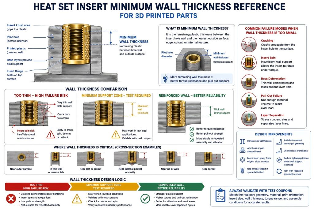
Why Minimum Wall Thickness Matters
A heat set insert works only if the surrounding plastic can hold the knurled brass body. During installation, the heated insert displaces softened plastic. During screw tightening, the plastic must resist rotation, axial pull-out, radial stress, and local compression.
If the remaining wall around the insert is too thin, the plastic may crack, deform, split along layer lines, or allow the insert to rotate. This can happen even when the pilot hole size and insert temperature are correct.
Minimum wall thickness is therefore a local support condition. It answers a simple question: after the insert hole is created, is there enough plastic left around it to carry the fastening load?
Minimum Wall Thickness vs Boss OD vs Edge Distance
These three design variables are connected, but they are not interchangeable.
| Design Variable | What It Describes | Main Question |
|---|---|---|
| Boss OD | The outside diameter of the raised boss around the insert | Is the boss large enough to support the insert? |
| Edge Distance | The distance from the insert or hole to a nearby outside edge | Is the insert too close to an edge or corner? |
| Minimum Wall Thickness | The remaining plastic between the hole wall and nearby surfaces | Is there enough plastic left around the hole? |
A part can have an acceptable boss diameter but still fail if a slot, cutout, thin wall, or internal pocket reduces the remaining wall thickness near the insert.
For related geometry references, see Boss OD Ratio for Heat Set Inserts in 3D Printed Parts and Heat Set Insert Edge Distance Reference for 3D Printed Parts.
Practical Wall Thickness Logic
There is no single wall thickness value that works for every insert and material. A small M2 insert in a lightly loaded PLA enclosure may need less surrounding material than an M5 insert in a service bracket exposed to vibration and repeated screw removal.
As a practical rule, the remaining wall thickness should increase when:
- the insert diameter increases
- the screw tightening torque increases
- the assembly is repeatedly opened and closed
- the part is exposed to vibration
- the material is brittle, soft, or prone to creep
- the insert is near an edge, corner, slot, or cutout
- the print orientation creates weak layer paths around the insert
The goal is not only to prevent immediate cracking. The wall must also keep the insert stable after repeated loading, screw removal, and long-term plastic relaxation.
Wall Thickness Sensitivity by Insert Size
Insert size strongly affects how much wall support is needed. Larger inserts require more surrounding material because they create higher radial stress during installation and usually carry higher screw torque.
| Insert Size | Wall Thickness Sensitivity | Main Risk When Wall Is Too Thin | Design Note |
|---|---|---|---|
| M2 | Very sensitive to small geometry changes | Small cracks, insert tilt, thread instability | Useful for compact parts, but thin walls leave little margin. |
| M2.5 | High sensitivity | Insert spin or local deformation | Needs controlled hole size and balanced wall support. |
| M3 | Moderate sensitivity | Boss cracking, wall splitting, torque loss | Common default size, but still needs sufficient support volume. |
| M4 | High structural demand | Wall breakout, boss splitting, edge cracking | Requires more plastic around the insert and better load distribution. |
| M5 | Very high structural demand | Large cracks, pull-out, long-term deformation | Should only be used when the printed structure has enough material volume. |
For insert size references, see M2 Heat Set Insert Dimensions Reference for 3D Printed Parts, M2.5 Heat Set Insert Dimensions Reference for 3D Printed Parts, M3 Heat Set Insert Dimensions Reference, M4 Heat Set Insert Dimensions Reference for 3D Printed Parts, and M5 Heat Set Insert Dimensions Reference for 3D Printed Parts.
What Happens When Wall Thickness Is Too Small
When the wall around a heat set insert is too thin, failure usually follows the shortest weak path through the printed plastic. The failure may appear during insert installation, during screw tightening, or after repeated service cycles.
- The insert may split the boss or wall during installation.
- The screw may tighten normally once, then loosen after the plastic relaxes.
- The insert may rotate when tightening torque is applied.
- A crack may form between the insert hole and the nearest surface.
- The boss may deform instead of holding preload.
- The insert may pull out under axial load.
- Layer separation may appear around the insert body.
For thin-wall failure behavior, see Why Do Heat Set Inserts Fail in Thin Wall 3D Printed Parts?.
Wall Thickness and Insert Installation
Wall thickness affects installation quality because heat set inserts displace softened plastic as they enter the hole. If the surrounding wall is thin, the displaced plastic has less volume to flow into and less structure to resist stress.
Thin walls are especially vulnerable when the insert is overheated, pushed in too quickly, misaligned, or installed into a hole that is too small. These conditions increase radial pressure and can crack the surrounding plastic before the screw is even installed.
For installation temperature behavior, see Heat Set Insert Installation Temperature for 3D Printed Parts.
Wall Thickness and Tightening Torque
During screw tightening, the plastic wall around the insert must resist rotational and radial stress. If the wall is too thin, the insert may spin or the boss may crack before the joint reaches useful preload.
Increasing screw torque does not fix weak wall support. It usually accelerates failure. A better solution is to increase local wall thickness, move the insert inward, add a boss or pad, reduce screw size, or redesign the load path.
For tightening behavior, see Heat Set Insert Torque Range Reference for 3D Printed Parts and Torque Resistance of Heat Set Inserts in 3D Printed Parts.
Wall Thickness and Pull-Out Strength
Pull-out strength depends on how much plastic surrounds the insert and how well that plastic is connected to the rest of the part. A thin wall may not provide enough material for the insert knurl to grip under axial load.
This is important in lids, brackets, service panels, fixtures, battery enclosures, robotics assemblies, and any part where the screw is repeatedly loaded or removed.
For axial load behavior, see Pull-Out Strength of Heat Set Inserts in 3D Printed Parts.
Material Behavior and Minimum Wall Thickness
Different materials need different wall support. A geometry that works in one material may fail in another because stiffness, ductility, temperature resistance, and creep behavior are different.
| Material | Wall Thickness Risk | Design Note |
|---|---|---|
| PLA | Brittle cracking when the wall is thin | Use generous wall support and avoid sharp stress paths. |
| PETG | Deformation and preload loss over time | Use thicker support for repeated assembly and vibration. |
| ABS | Layer splitting or local deformation | Use proper print orientation and rounded transitions. |
| ASA | Similar to ABS with better outdoor stability | Still needs adequate wall support near inserts. |
| Nylon | Flexible movement around the insert | Check torque retention and long-term preload stability. |
| Fiber-filled materials | Stiff but direction-sensitive | Avoid brittle wall breakout along weak print paths. |
For material comparison, see PLA vs PETG vs ABS for Threaded Inserts.
Design Improvements for Thin Wall Conditions
If the remaining wall thickness around an insert is limited, the design should add local support instead of simply accepting a fragile fastening point.
- Increase the local wall thickness around the insert.
- Add a boss or reinforced pad around the insert location.
- Move the insert farther from the outside surface or edge.
- Use ribs to connect the insert area to stronger part geometry.
- Use fillets to reduce stress concentration at boss bases and wall transitions.
- Use a smaller insert when part geometry cannot support a larger one.
- Reduce tightening torque if the wall support is limited.
- Avoid placing inserts near slots, cutouts, thin tabs, or sharp corners.
- Validate repeated assembly cycles if the screw will be removed often.
For boss design principles, see How to Design Bosses for Heat Set Inserts.
Wall Thickness Around Internal Cutouts
Minimum wall thickness should also be checked around internal features. A cable slot, vent opening, pocket, clearance channel, or internal cutout can reduce plastic support even when the outside of the part looks strong.
When an insert is placed near a cutout, the remaining wall between the hole and the opening should be treated like an edge condition. The insert may crack toward the opening or lose torque resistance on the unsupported side.
Common Mistakes
Checking only the outside dimensions of the part
A part may look thick from the outside but still have an internal pocket or cutout that leaves very little plastic around the insert hole.
Using the largest insert that fits
A larger insert reduces remaining wall thickness. If the surrounding plastic becomes too thin, the larger insert can make the joint weaker, not stronger.
Ignoring installation pressure
Many failures begin during heat insertion, before any screw load is applied. Thin walls are more likely to crack when the insert is overheated, misaligned, or forced into an undersized hole.
Assuming one successful assembly proves the wall is safe
Thin wall problems often appear after repeated screw removal, vibration, temperature changes, or long-term preload relaxation.
Test Coupon Method
The best way to validate minimum wall thickness is to print a test coupon that reproduces the real wall condition. A solid block test is not enough if the final part uses a thin wall, narrow tab, edge boss, internal slot, or cutout near the insert.
The test coupon should match:
- the same insert size and insert length
- the same pilot hole diameter and hole depth
- the same remaining wall thickness around the hole
- the same boss or pad geometry
- the same nearby edges, slots, or cutouts
- the same printed material and print orientation
- the same screw engagement length
- the same tightening torque range
- the same repeated assembly condition
After testing, inspect for wall cracking, insert spin, boss deformation, pull-out movement, and preload loss after repeated screw cycles.
FAQ
What is minimum wall thickness for heat set inserts?
Minimum wall thickness is the remaining printed plastic between the insert hole wall and the nearest outside surface, edge, cutout, boss side, or internal feature. It determines how much local plastic support remains around the insert.
Is minimum wall thickness the same as boss diameter?
No. Boss diameter describes the full outside size of the boss. Minimum wall thickness describes the remaining plastic outside the insert hole. A boss can look large but still have weak local wall support if a cutout or edge is nearby.
Why does a thin wall crack during heat set insert installation?
The heated insert softens and displaces plastic. If the surrounding wall is too thin, the plastic cannot absorb the expansion and installation pressure, so it may split or deform.
Can I use a larger insert to make a thin wall stronger?
Usually not. A larger insert removes more plastic and increases stress. If the part has limited wall thickness, a smaller insert or reinforced geometry is often safer.
Does wall thickness affect repeated assembly?
Yes. Thin walls are more likely to lose preload, deform, or allow insert movement after repeated screw removal and tightening cycles.
Related Guides
- Boss OD Ratio for Heat Set Inserts in 3D Printed Parts
- Heat Set Insert Edge Distance Reference for 3D Printed Parts
- Heat Set Insert Torque Range Reference for 3D Printed Parts
- How to Design Bosses for Heat Set Inserts
- Pull-Out Strength of Heat Set Inserts in 3D Printed Parts
- Torque Resistance of Heat Set Inserts in 3D Printed Parts
- Heat Set Insert Installation Temperature for 3D Printed Parts
- Why Do Heat Set Inserts Fail in Thin Wall 3D Printed Parts?