
Heat Set Insert Pilot Hole Tolerance Reference for 3D Printed Parts explains how printed hole variation affects heat set insert installation, torque resistance, pull-out strength, boss cracking, and long-term fastening reliability.
Designing the correct pilot hole size is only the first step. In real 3D printed parts, the hole that comes off the printer may not match the CAD diameter. Material shrinkage, slicer behavior, printer calibration, extrusion width, cooling, layer height, and post-processing can all change the actual hole size.
This reference focuses on pilot hole tolerance: how much variation can be accepted before the insert becomes too loose, too tight, difficult to install, or likely to damage the surrounding plastic.
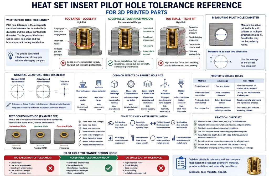
Why Pilot Hole Tolerance Matters
A heat set insert depends on controlled interference between the brass insert and the printed plastic. If the pilot hole is slightly smaller than the insert body, the heated insert can displace softened plastic and form a strong grip around the knurl pattern. If the hole is too large, the insert may not have enough plastic contact. If the hole is too small, installation pressure may crack the boss or push too much plastic out of the hole.
This is why the actual printed hole must be checked, not only the CAD hole diameter.
For general hole sizing principles, see Heat Set Insert Hole Size Guide.
Pilot Hole Size vs Pilot Hole Tolerance
Pilot hole size and pilot hole tolerance are related, but they are not the same thing.
| Term | Meaning | Design Question |
|---|---|---|
| Pilot hole size | The intended hole diameter used in CAD or design documentation | What diameter should the insert hole be? |
| Pilot hole tolerance | The acceptable variation between intended hole size and actual printed hole size | How much printed hole error can the insert still tolerate? |
| Actual printed hole | The real measured hole after printing or post-processing | Does the printed part match the usable tolerance window? |
A design can use a correct nominal hole size but still fail if the actual printed holes vary too much across parts, printers, materials, or orientations.
What Happens When the Hole Is Too Large
An oversized pilot hole reduces the contact pressure between the insert knurl and the surrounding plastic. During installation, the insert may drop in too easily, sit loosely, or fail to form a strong mechanical grip.
Common symptoms of an oversized pilot hole include:
- the insert feels loose immediately after installation
- the insert rotates when the screw is tightened
- the insert pulls out under axial load
- the joint loses preload after repeated screw removal
- the insert sits unevenly because the plastic does not support it uniformly
- the screw tightens at first but the insert later moves inside the boss
For a dedicated failure explanation, see Why Do Heat Set Inserts Fail When the Hole Is Too Large?.
What Happens When the Hole Is Too Small
An undersized pilot hole increases insertion pressure. The insert may require too much force, displace excessive plastic, deform the hole, or crack the surrounding boss. In small bosses or thin walls, this can damage the part before the screw is ever installed.
Common symptoms of an undersized pilot hole include:
- the insert is difficult to press into the hole
- plastic bulges around the insert opening
- the boss cracks during installation
- the insert does not seat fully
- the insert tilts because the plastic resists unevenly
- the bottom of the hole fills with displaced plastic
- thread access becomes blocked or distorted
For a dedicated failure explanation, see Why Do Heat Set Inserts Fail When the Hole Is Too Small?.
Why Printed Holes Often Do Not Match CAD
3D printed holes are affected by more than the CAD diameter. Small circular holes often print undersized because extrusion paths, corner compensation, material flow, cooling, and slicer settings change the real geometry.
The difference becomes more important with heat set inserts because the hole is not only a clearance feature. It is part of the mechanical retention system.
| Cause | Effect on Pilot Hole | Possible Insert Risk |
|---|---|---|
| Over-extrusion | Hole prints smaller | High insertion force, boss cracking |
| Under-extrusion | Hole may print larger or less supported | Loose insert, poor knurl grip |
| Material shrinkage | Hole dimension shifts after cooling | Unpredictable fit across materials |
| Slicer hole compensation | Hole may enlarge or shrink depending on settings | Variation between print profiles |
| Layer height and wall count | Changes hole surface quality and wall stiffness | Uneven insertion and weak support |
| Print orientation | Changes roundness and layer support | Insert tilt, weak torque resistance |
| Nozzle size | Affects minimum feature accuracy | Small holes may be inaccurate |
Material Influence on Pilot Hole Tolerance
Different materials tolerate hole variation differently. Some materials crack when the hole is too tight. Others deform or relax when the hole is too loose. The same nominal pilot hole may behave differently in PLA, PETG, ABS, ASA, nylon, or fiber-filled materials.
| Material | Typical Tolerance Behavior | Design Note |
|---|---|---|
| PLA | Stiff and dimensionally stable, but brittle | Too-small holes can crack bosses quickly. |
| PETG | Tough but prone to deformation and creep | Loose holes may lose preload over time. |
| ABS | More heat-tolerant, but shrinkage and warping matter | Measure actual holes after cooling. |
| ASA | Similar to ABS with better outdoor stability | Check repeatability across print batches. |
| Nylon | Ductile and flexible | May tolerate insertion but relax under load. |
| Fiber-filled materials | Stiff and abrasive, often direction-sensitive | Hole accuracy and brittleness both need validation. |
For material comparison, see PLA vs PETG vs ABS for Threaded Inserts.
Printed Hole vs Drilled Hole
Some designers print pilot holes directly. Others print undersized holes and drill or ream them afterward. Both methods can work, but they produce different tolerance behavior.
| Method | Advantage | Risk |
|---|---|---|
| Printed hole only | Fast and simple | Hole size depends heavily on printer, slicer, and material behavior. |
| Printed undersized, then drilled | More consistent diameter | Drilling can remove useful surface texture or weaken thin walls if misaligned. |
| Printed undersized, then reamed | Better dimensional control | Requires careful tool alignment and repeatable process. |
| Printed test coupon first | Best for validating production settings | Requires extra setup but reduces assembly failures. |
For small batches, printed holes may be acceptable after test validation. For repeated production, post-processing or calibrated hole compensation may improve consistency.
How to Judge an Acceptable Pilot Hole Tolerance Window
The useful tolerance window sits between two failure zones. On one side, the hole is too large and the insert becomes loose. On the other side, the hole is too small and the plastic cracks or deforms during insertion.
A practical tolerance window should satisfy all of these conditions:
- the insert can be installed straight without excessive force
- the insert seats fully without bottoming against displaced plastic
- the boss does not crack or bulge during installation
- the insert does not rotate under the intended tightening torque
- the insert resists pull-out under the expected assembly load
- the joint retains preload after repeated screw cycles
- the result is repeatable across several printed samples
For tightening validation, see Heat Set Insert Torque Range Reference for 3D Printed Parts.
Pilot Hole Tolerance and Hole Depth
Hole tolerance also interacts with hole depth. If the hole is too shallow, the insert may bottom out before it seats correctly. If the hole is too small and too shallow, displaced plastic can collect below the insert and block full seating.
A correct diameter with insufficient depth can still produce a failed installation. Likewise, a good depth cannot compensate for a hole that is far outside the usable tolerance window.
For depth reference, see Heat Set Insert Hole Depth Chart for 3D Printed Parts.
Pilot Hole Tolerance and Boss Geometry
A tight tolerance window is harder to maintain when the boss is small, thin, near an edge, or close to a cutout. In these cases, small hole errors can have a large effect because the surrounding plastic support is already limited.
For stronger insert performance, hole tolerance should be evaluated together with boss outside diameter, edge distance, and minimum wall thickness.
For related references, see Boss OD Ratio for Heat Set Inserts in 3D Printed Parts, Heat Set Insert Edge Distance Reference for 3D Printed Parts, and Heat Set Insert Minimum Wall Thickness Reference for 3D Printed Parts.
Common Mistakes
Trusting the CAD hole without measuring the printed part
The CAD hole is only the intended geometry. The printed hole may be smaller, larger, oval, rough, or inconsistent across parts.
Testing only one printed sample
One successful insert does not prove the tolerance window is safe. Test several samples across the same print settings and material batch.
Using the same hole tolerance for every material
PLA, PETG, ABS, ASA, nylon, and fiber-filled materials behave differently during heating, insertion, cooling, and tightening.
Ignoring post-processing effects
Drilling, reaming, sanding, or cleaning the hole can change both diameter and surface contact. These steps should be part of the tested process, not added afterward without validation.
Assuming loose installation can be fixed with more torque
If the insert is loose because the hole is too large, increasing screw torque can make the insert spin faster. The hole tolerance problem must be fixed at the geometry or process level.
Test Coupon Method
The best way to validate pilot hole tolerance is to print a small set of test coupons with controlled hole variations. The coupon should match the real part material, print orientation, boss geometry, wall thickness, and insert installation method.
A useful test coupon set can include:
- the nominal pilot hole size
- one slightly smaller hole
- one slightly larger hole
- the same hole depth as the final part
- the same boss outside diameter or local wall support
- the same insert size and insert length
- the same screw engagement length
- the same tightening torque used in assembly
- several repeated samples to check consistency
After installation, inspect each sample for insertion force, seating quality, plastic bulging, cracking, insert spin, pull-out movement, and preload loss after repeated screw cycles.
Practical Design Checklist
- Measure actual printed holes, not only CAD dimensions.
- Validate the hole tolerance window for each material and print profile.
- Check both too-large and too-small failure behavior.
- Use test coupons before committing to production parts.
- Keep hole tolerance, hole depth, boss OD, edge distance, and wall thickness consistent.
- Do not use screw torque to compensate for a loose insert.
- Do not force an insert into a hole that creates boss cracking or plastic bulging.
- Retest after changing printer, nozzle, slicer profile, material, or orientation.
FAQ
What is pilot hole tolerance for heat set inserts?
Pilot hole tolerance is the acceptable variation between the intended pilot hole diameter and the actual printed hole diameter. It defines how much hole error the insert can tolerate before installation or fastening reliability becomes unsafe.
Why are my printed holes smaller than the CAD diameter?
Printed holes often become smaller because of extrusion width, slicer behavior, material flow, cooling, and printer calibration. Small circular holes are especially sensitive to these effects.
Is a tighter hole always better for heat set inserts?
No. A hole that is too tight can crack the boss, deform the part, tilt the insert, or prevent full seating. The goal is controlled interference, not maximum insertion force.
Should heat set insert holes be drilled after printing?
Drilling or reaming can improve diameter consistency, but it must be validated. Poor alignment or excessive material removal can weaken the hole or reduce insert grip.
How do I test the correct pilot hole tolerance?
Print test coupons with slightly different hole sizes, install inserts using the same process as the final part, then check seating quality, cracking, insert spin, pull-out resistance, and repeated assembly performance.
Related Guides
- Heat Set Insert Hole Size Guide
- Heat Set Insert Hole Depth Chart for 3D Printed Parts
- Heat Set Insert Installation Temperature for 3D Printed Parts
- Boss OD Ratio for Heat Set Inserts in 3D Printed Parts
- Heat Set Insert Edge Distance Reference for 3D Printed Parts
- Heat Set Insert Minimum Wall Thickness Reference for 3D Printed Parts
- Why Do Heat Set Inserts Fail When the Hole Is Too Large?
- Why Do Heat Set Inserts Fail When the Hole Is Too Small?
Related Decision Resources
For insert selection, tool choice, and supplier comparison, use these decision-focused references after the engineering requirements are defined.