
Heat Set Insert Seating Depth Reference for 3D Printed Parts explains how the final installed position of a heat set insert affects screw engagement, surface contact, torque resistance, thread access, and assembly reliability.
Hole depth and seating depth are related, but they are not the same. Hole depth describes how deep the printed hole is. Seating depth describes where the insert actually ends up after installation: flush with the surface, slightly below the surface, proud above the surface, tilted, or bottomed out inside the hole.
A heat set insert can use the correct hole size, correct hole depth, and correct installation temperature, but still fail if the insert is not seated properly. Poor seating can cause loose assemblies, poor clamping, blocked threads, tilted screws, surface gaps, and repeated service problems.
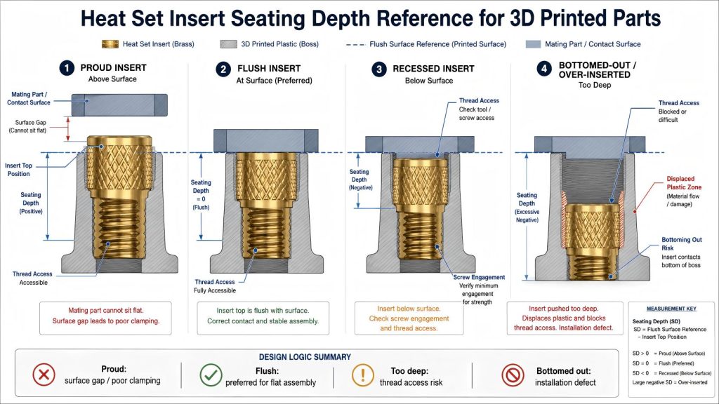
Why Seating Depth Matters
When a heat set insert is installed into a 3D printed part, the final position controls how the screw enters the insert and how the assembled part contacts the printed surface. If the insert is too high, it may prevent mating parts from sitting flat. If it is too low, the screw may lose engagement length or the top surface may deform under clamping load.
Seating depth also affects whether the insert is fully supported by the surrounding plastic. An insert that is only partially inserted may have weak knurl engagement. An insert that is pushed too deep may bottom out, displace too much plastic, or distort the hole.
For hole depth planning, see Heat Set Insert Hole Depth Chart for 3D Printed Parts.
Seating Depth vs Hole Depth
Hole depth is a design feature. Seating depth is an installation result. A correct hole depth gives the insert enough space to seat properly, but it does not guarantee correct seating.
| Term | What It Describes | Main Question |
|---|---|---|
| Hole depth | The depth of the printed pilot hole | Is the hole deep enough for the insert? |
| Insert length | The physical length of the heat set insert | Can the insert fit without bottoming out? |
| Seating depth | The final installed position of the insert relative to the part surface | Is the insert flush, proud, too deep, or tilted? |
| Thread access | The usable thread path available to the screw after installation | Can the screw engage correctly? |
A good insert installation needs all four conditions to work together: the hole must be deep enough, the insert must fit, the seating position must be controlled, and the screw must have usable thread access.
Common Seating Conditions
Heat set inserts usually fall into several seating conditions after installation. Each condition affects the assembly differently.
| Seating Condition | What It Looks Like | Main Risk | Engineering Judgment |
|---|---|---|---|
| Flush seating | Insert top is level with the printed surface | Low risk when installation is straight and stable | Usually preferred for flat mating surfaces and clean assembly. |
| Slightly below surface | Insert top sits just under the printed surface | Possible reduced thread access or surface compression | May be acceptable if screw engagement remains sufficient. |
| Proud above surface | Insert top stands above the printed surface | Mating part may not sit flat | Usually undesirable for stacked assemblies or covers. |
| Over-inserted | Insert is pushed too deep into the hole | Thread access loss, plastic displacement, weak clamping | Needs review, especially if screw length is fixed. |
| Under-inserted | Insert is not fully seated | Poor knurl engagement, surface interference | High risk for loose inserts or uneven assembly. |
| Tilted insert | Insert axis is not perpendicular to the surface | Screw misalignment, thread damage, uneven load | Reject or rework if screw alignment matters. |
| Bottomed-out insert | Insert reaches the bottom before fully seating | Incomplete seating, plastic bulging, blocked threads | Usually indicates insufficient hole depth or displaced plastic. |
Flush Seating
Flush seating is usually the cleanest installation condition. The insert top is level with the printed surface, allowing mating parts, lids, brackets, covers, and service panels to sit flat.
Flush seating is especially useful when the screw passes through another component before entering the insert. If the insert is proud above the surface, the upper component may contact the insert instead of the printed face, creating uneven clamping.
However, flush seating still needs enough thread engagement below the surface. A flush insert in a shallow hole may look correct from the outside but still provide weak screw engagement.
For screw engagement planning, see Screw Engagement Length for Heat Set Inserts in 3D Printed Parts.
When the Insert Sits Proud Above the Surface
A proud insert stands above the printed surface. This may happen when the insert is not heated enough, the hole is too small, the installation force stops too early, or displaced plastic blocks the insert from seating fully.
A proud insert can create several assembly problems:
- the mating part does not sit flat
- clamping load concentrates around the insert instead of the printed surface
- the screw may enter at a slight angle
- the top component may rock or gap during tightening
- the joint may loosen after vibration or repeated handling
If a design requires a flat contact surface, proud inserts should usually be treated as installation defects.
When the Insert Sits Too Deep
An insert that sits too deep may look neat from the outside, but it can reduce usable thread engagement and change how the screw clamps the assembly. If the screw is too short, it may not engage enough threads. If the screw is too long, it may bottom out against plastic or the bottom of the hole.
Over-insertion can also displace too much plastic around the insert body. This may weaken the surrounding wall, create plastic bulging, or reduce the support around the knurl area.
For minimum wall support, see Heat Set Insert Minimum Wall Thickness Reference for 3D Printed Parts.
Bottoming Out During Installation
Bottoming out happens when the insert reaches the bottom of the hole before it reaches the intended seating position. This is different from controlled full seating. A bottomed-out insert may stop because the hole is too shallow, displaced plastic has collected below the insert, or the insert length does not match the hole depth.
Warning signs of bottoming out include:
- the insert stops before becoming flush
- extra force causes boss bulging or cracking
- plastic appears pushed up around the insert
- the screw cannot fully engage the threads
- the insert feels unstable after installation
If bottoming out occurs, do not simply push harder. Review hole depth, insert length, pilot hole tolerance, installation temperature, and displaced plastic volume.
Tilted Seating and Screw Alignment
A tilted insert can create more problems than a slightly high or low insert. If the insert axis is not aligned with the screw direction, the screw may cross-thread, bind, damage the internal thread, or create uneven load on one side of the boss.
Tilted seating often comes from poor installation alignment, uneven heat, oval holes, rough printed holes, or unsupported boss geometry. It is more common in small inserts, thin walls, and parts printed with inconsistent hole roundness.
For pilot hole variation, see Heat Set Insert Pilot Hole Tolerance Reference for 3D Printed Parts.
Seating Depth and Surface Contact
Many heat set insert assemblies depend on flat surface contact. Lids, covers, panels, brackets, fixture plates, and electronics housings often need the upper component to sit evenly on the printed part.
If the insert is proud, the upper component may contact the insert instead of the surrounding plastic. If the insert is too deep, the screw may pull the upper component downward unevenly or compress the printed surface around the hole.
Good seating depth helps the screw preload travel through the intended contact surfaces instead of through a distorted insert location.
Seating Depth and Thread Access
The insert must be seated deep enough to stay secure, but not so deep that the screw loses usable thread engagement. Thread access depends on insert length, screw length, seating depth, and whether plastic has blocked part of the insert during installation.
If molten plastic enters the insert threads or collects at the bottom of the hole, the screw may not engage smoothly. This can feel like a screw length problem, but the root cause may be seating depth or installation quality.
Material Behavior and Seating Depth
Different printed materials respond differently during insert seating. The same installation depth target may behave differently in PLA, PETG, ABS, ASA, nylon, or filled materials.
| Material | Seating Behavior | Common Risk |
|---|---|---|
| PLA | Seats cleanly when controlled, but cracks if forced | Boss cracking, brittle surface damage |
| PETG | Softens and flows more, but may deform around the insert | Plastic bulging, preload loss, uneven seating |
| ABS | Better heat tolerance, but shrinkage and warping matter | Inconsistent seating across printed batches |
| ASA | Similar to ABS with better outdoor stability | Needs controlled heat and pressure |
| Nylon | Ductile and flexible | Insert movement or relaxed seating under load |
| Fiber-filled materials | Stiffer but more brittle locally | Cracking or rough seating if forced |
For material comparison, see PLA vs PETG vs ABS for Threaded Inserts.
Installation Factors That Affect Seating Depth
Seating depth is affected by geometry, material, and installation process. A repeatable process is important when multiple inserts must sit at the same height across an assembly.
| Factor | Possible Effect | Risk |
|---|---|---|
| Installation temperature | Too low prevents full seating; too high over-softens plastic | Proud insert, over-insertion, plastic deformation |
| Pilot hole tolerance | Too small increases resistance; too large reduces support | Under-insertion, cracking, loose insert |
| Hole depth | Too shallow causes bottoming out | Incomplete seating, blocked thread access |
| Insertion alignment | Off-axis pressure tilts the insert | Screw misalignment, thread damage |
| Insert length | Long inserts need more depth and support | Bottoming out or insufficient wall support |
| Print orientation | Layer direction changes boss stiffness | Cracking, deformation, tilted seating |
For installation temperature behavior, see Heat Set Insert Installation Temperature for 3D Printed Parts.
How to Check Seating Depth
Seating depth should be checked visually and mechanically. A clean top surface is not enough if the insert is tilted, blocked internally, or weakly supported by plastic.
- Check whether the insert top is flush, proud, or below the printed surface.
- Check whether the insert axis is straight and perpendicular to the surface.
- Confirm that the screw enters smoothly without cross-threading.
- Confirm that the mating part sits flat against the printed surface.
- Check that the screw has enough engagement length after seating.
- Inspect for plastic bulging, surface distortion, or boss cracking.
- Repeat the check after several screw removal and tightening cycles.
Test Coupon Method
The best way to validate seating depth is to print a test coupon that matches the real part geometry and installation process. Seating behavior can change when the boss diameter, wall thickness, hole depth, material, or print orientation changes.
A useful seating depth test coupon should include:
- the same insert size and insert length
- the same pilot hole diameter and tolerance condition
- the same hole depth
- the same boss diameter or wall support
- the same printed material and print orientation
- the same installation tool and temperature
- the same intended screw length
- the same assembly stack thickness, if possible
After installation, check flushness, thread access, screw engagement, insert tilt, surface contact, and repeated assembly behavior.
Common Mistakes
Assuming flush appearance means the insert is correct
An insert can look flush but still have poor thread access, plastic blocking the internal thread, or weak support around the knurl body.
Pushing harder when the insert stops
If the insert stops early, it may be bottoming out or the hole may be too tight. Extra force can crack the boss or deform the printed surface.
Ignoring proud inserts in stacked assemblies
A proud insert can prevent a lid, panel, or bracket from sitting flat. This can create uneven preload and loose joints.
Using the same seating target for every part
Some assemblies need flush inserts. Others may tolerate slightly recessed inserts. The correct seating condition depends on screw length, surface contact, and assembly stack design.
Not checking repeated assembly
An insert may seat correctly at first but move after repeated screw removal if the surrounding plastic support is weak.
Design Checklist
- Design enough hole depth for the insert length and displaced plastic.
- Use a controlled pilot hole tolerance to avoid under-insertion or loose seating.
- Install the insert straight and perpendicular to the surface.
- Avoid forcing the insert after it stops unexpectedly.
- Check that the insert does not sit proud when a flat mating surface is required.
- Verify screw engagement after the insert is installed, not only before.
- Inspect for plastic bulging, cracking, or blocked thread access.
- Validate seating depth with real test coupons before production use.
FAQ
What is seating depth for heat set inserts?
Seating depth is the final installed position of the insert relative to the printed part surface. It describes whether the insert is flush, proud, recessed, tilted, or bottomed out after installation.
Is seating depth the same as hole depth?
No. Hole depth is the depth of the printed pilot hole. Seating depth is the final position of the insert after installation. A correct hole depth helps seating, but it does not guarantee correct seating.
Should heat set inserts be flush with the surface?
Flush seating is usually preferred when another part must sit flat on the printed surface. Slightly recessed seating may be acceptable if screw engagement remains sufficient and the assembly still clamps correctly.
What happens if a heat set insert sits too high?
A proud insert can prevent the mating part from sitting flat, concentrate clamping load around the insert, create gaps, and reduce assembly stability.
What happens if a heat set insert is pushed too deep?
Over-insertion can reduce thread access, block screw engagement, displace too much plastic, weaken the surrounding wall, or cause poor clamping.
Related Guides
- Heat Set Insert Hole Depth Chart for 3D Printed Parts
- Heat Set Insert Pilot Hole Tolerance Reference for 3D Printed Parts
- Heat Set Insert Installation Temperature for 3D Printed Parts
- Screw Engagement Length for Heat Set Inserts in 3D Printed Parts
- Heat Set Insert Minimum Wall Thickness Reference for 3D Printed Parts
- Heat Set Insert Torque Range Reference for 3D Printed Parts
- Why Do Threads Become Loose in Heat Set Inserts?
- Why Do Threaded Inserts Loosen After Repeated Screw Removal?