
M3 brass heat set inserts for 3D printed parts are one of the most commonly used threaded insert sizes for functional printed assemblies. They are often used in electronics enclosures, robotics parts, fixtures, service panels, brackets, battery covers, and modular prototypes where printed plastic threads would wear out too quickly.
An M3 heat set insert is not only a small brass component. In a 3D printed part, it becomes part of a fastening system that includes the insert body, knurl pattern, pilot hole, boss geometry, screw engagement length, tightening torque, material behavior, and assembly stack-up.
This product reference explains how to understand M3 brass heat set inserts from an engineering design perspective. It is not a brand recommendation or purchasing list. The goal is to help designers read M3 insert specifications and connect them to printed part design decisions.
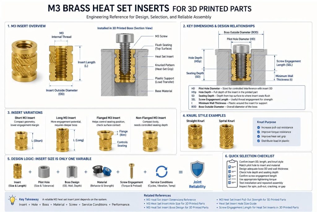
What Is an M3 Brass Heat Set Insert?
An M3 brass heat set insert is a threaded metal insert with an internal M3 thread. It is installed into a printed plastic part using heat, allowing the surrounding plastic to soften and flow around the insert’s knurled exterior.
After cooling, the insert provides a reusable metal thread inside the printed part. This allows screws to be installed, removed, and tightened more reliably than directly threading into printed plastic.
M3 inserts are popular because they offer a useful balance between compact size and practical fastening strength. They are small enough for many printed enclosures and brackets, but large enough for repeated assembly in many functional prototypes.
Where M3 Heat Set Inserts Are Commonly Used
M3 brass inserts are commonly used in 3D printed parts where screws need to be removed more than once or where plastic threads are not reliable enough.
- electronics enclosure covers
- robotics service panels
- sensor brackets and camera mounts
- battery access panels
- fixture plates and replaceable wear components
- modular prototype assemblies
- small machine covers and inspection panels
- printed parts exposed to vibration or repeated handling
For application examples, see Heat Set Inserts for Electronics Enclosure Lid Cycling, Heat Set Inserts for Robot Joint Service Panels, and Heat Set Inserts for Printed Jigs with Replaceable Wear Plates.
Why M3 Is a Common Default Size
M3 is often chosen as a default insert size because it fits many medium-small 3D printed structures. It is large enough to provide useful thread engagement, but not so large that it always requires heavy bosses or thick walls.
However, M3 should not be treated as automatically correct. The right insert size depends on load, screw torque, available wall thickness, boss diameter, edge distance, material, and whether the assembly will be opened repeatedly.
| Design Need | Why M3 Often Works | When to Reconsider |
|---|---|---|
| Small functional enclosure | M3 provides stronger reusable threads than printed plastic alone. | Use smaller inserts if the wall or boss is too narrow. |
| Repeated service access | M3 screws are practical for covers and panels. | Check preload loss and screw engagement after cycles. |
| Moderate clamp load | M3 can support many light-to-medium assemblies. | Use larger inserts only if the printed structure can support them. |
| Compact bracket or mount | M3 is easier to fit than M4 or M5. | Check vibration, torque, and boss cracking risk. |
Reading M3 Insert Specifications
When comparing M3 heat set inserts, the most important specifications are not only the internal thread size. Designers should also check the insert outside diameter, insert length, knurl pattern, flange style, and recommended hole size.
| Specification | What It Means | Why It Matters in Printed Parts |
|---|---|---|
| Internal thread | The screw thread size, usually M3 | Determines screw compatibility. |
| Insert outside diameter | The outer body size of the insert | Affects pilot hole size and boss diameter. |
| Insert length | The axial length of the brass insert | Affects hole depth, screw engagement, and pull-out strength. |
| Knurl pattern | The textured exterior that grips plastic | Affects torque resistance and pull-out behavior. |
| Flange | A wider top rim on some insert designs | Can help seating control but may affect surface contact. |
| Installation direction | How the insert is designed to enter the plastic | Affects seating, alignment, and knurl engagement. |
For dimensional reference, see M3 Heat Set Insert Dimensions Reference.
Short vs Long M3 Heat Set Inserts
M3 inserts are available in different lengths. A short M3 insert is easier to fit into compact parts, but it usually provides less pull-out resistance and less thread engagement. A longer M3 insert can improve load capacity, but it requires more hole depth, more boss height, and more surrounding plastic support.
| Insert Type | Typical Advantage | Design Risk |
|---|---|---|
| Short M3 insert | Fits compact bosses and thinner parts | Lower pull-out resistance and less thread engagement margin. |
| Medium M3 insert | Useful balance for many printed assemblies | Still needs proper hole depth and boss support. |
| Long M3 insert | More thread engagement and better axial support potential | Needs taller boss, deeper hole, and enough material around the insert. |
A longer insert is not automatically stronger if the printed boss cannot support it. Insert length must match the printed geometry, not only the screw size.
For screw engagement design, see Screw Engagement Length for Heat Set Inserts in 3D Printed Parts.
M3 Insert Hole Size Relationship
The pilot hole for an M3 heat set insert must allow controlled interference between the insert and the plastic. If the hole is too large, the insert may not grip. If the hole is too small, the boss may crack during installation.
The correct pilot hole depends on the actual insert outside diameter, knurl geometry, printed material, printer accuracy, and whether holes are printed directly or post-processed.
For general hole sizing, see Heat Set Insert Hole Size Guide. For M3-specific hole behavior, see M3 Heat Set Insert Hole Size for 3D Printed Parts and Heat Set Insert Pilot Hole Tolerance Reference for 3D Printed Parts.
M3 Insert Boss Design
An M3 insert needs enough surrounding plastic to resist installation pressure, screw tightening torque, pull-out force, and repeated assembly. A correctly sized insert can still fail if the boss is too thin, too close to an edge, or poorly oriented relative to print layers.
Boss design should account for:
- boss outside diameter
- minimum wall thickness around the insert hole
- edge distance from nearby boundaries
- hole depth and seating depth
- material behavior under heat and torque
- print orientation around the boss
- expected screw torque and service cycles
For boss design, see M3 Heat Set Insert Boss Design for 3D Printed Parts, How to Design Bosses for Heat Set Inserts, and Boss OD Ratio for Heat Set Inserts in 3D Printed Parts.
Flanged vs Non-Flanged M3 Inserts
Some M3 heat set inserts have a flange or wider top rim. Others are straight-bodied without a flange. Both can work, but they affect seating and surface contact differently.
| Insert Style | Potential Benefit | Design Caution |
|---|---|---|
| Non-flanged M3 insert | Simple body shape and compact seating | Needs careful seating depth control to avoid sinking or proud placement. |
| Flanged M3 insert | Can help control top seating position | The flange may affect mating surface contact if not recessed or designed around. |
| Knurled M3 insert | Improves grip in softened plastic | Needs correct pilot hole and wall support. |
For seating behavior, see Heat Set Insert Seating Depth Reference for 3D Printed Parts.
Material Compatibility
M3 brass heat set inserts behave differently depending on the printed material. The insert may be the same, but the surrounding plastic controls much of the final strength and reliability.
| Material | M3 Insert Behavior | Design Note |
|---|---|---|
| PLA | Stiff and easy to print, but brittle and heat-sensitive | Use conservative torque and avoid thin bosses. |
| PETG | Tougher than PLA, but prone to creep and preload loss | Check repeated assembly and torque retention. |
| ABS | Better heat resistance than PLA | Control warping and layer adhesion around bosses. |
| ASA | Useful for outdoor or exposed parts | Maintain wall support and avoid edge-heavy insert placement. |
| Nylon | Ductile and fatigue-tolerant | Check preload relaxation and flexible movement around the insert. |
| Fiber-filled materials | Stiff and dimensionally stable, but locally brittle | Avoid point loading and validate installation pressure. |
For material comparison, see PLA vs PETG vs ABS for Threaded Inserts.
When M3 Is Appropriate
M3 brass heat set inserts are often appropriate when the printed part has enough boss diameter, enough wall thickness, and enough depth to support the insert without cracking or deforming.
M3 is usually a good candidate for:
- small-to-medium printed enclosures
- service covers and access panels
- robotics brackets and joint panels
- fixtures with replaceable components
- prototype assemblies that require repeated screw removal
- sensor and camera mounts with moderate loads
For repeated assembly examples, see Heat Set Inserts for Repeated Assembly in 3D Printed Parts.
When M3 May Not Be Enough
M3 is not always the right size. If the assembly carries high load, high vibration, large bending moment, or frequent service cycles, the designer may need a larger insert, more inserts, better load distribution, or a different fastening structure.
M3 may be insufficient when:
- the joint carries high structural load
- the screw must resist strong vibration
- the boss is repeatedly loaded in bending
- the printed material creeps under clamp load
- the insert is close to an edge or thin wall
- the screw engagement length is too short
- the part requires high tightening torque
For torque behavior, see Heat Set Insert Torque Range Reference for 3D Printed Parts and Torque Resistance of Heat Set Inserts in 3D Printed Parts.
Common Mistakes When Choosing M3 Inserts
Choosing M3 because it is common
M3 is common, but the printed part still needs enough plastic support. A familiar screw size does not guarantee a reliable insert joint.
Ignoring insert length
Two M3 inserts can have different lengths and outside diameters. The same screw size does not mean the same hole depth, boss height, or pull-out behavior.
Using the same pilot hole for every M3 insert
Different insert brands and knurl styles may require different hole sizes. The actual insert geometry should be measured and tested.
Placing M3 inserts too close to edges
M3 inserts still need edge distance and wall support. If the insert is placed in a narrow tab or near a sharp corner, the boss can crack or the insert can spin.
Overtightening to compensate for weak geometry
If the insert is loose or the cover does not clamp properly, more torque often makes the problem worse. The real issue may be pilot hole tolerance, seating depth, stack-up, or wall support.
Engineering Checklist for M3 Brass Heat Set Inserts
- Confirm the actual insert outside diameter and length.
- Match the pilot hole to the insert geometry and material.
- Check printed hole tolerance with test coupons.
- Design enough boss diameter and wall thickness.
- Keep the insert away from weak edges and sharp corners.
- Check seating depth after installation.
- Confirm screw engagement length after the full assembly stack-up.
- Use controlled tightening torque rather than forcing the screw.
- Test repeated assembly if the screw will be removed often.
- Inspect for insert spin, pull-out movement, cracking, and preload loss.
FAQ
What are M3 brass heat set inserts used for in 3D printed parts?
M3 brass heat set inserts are used to add reusable metal threads to 3D printed parts. They are commonly used in enclosures, brackets, service panels, fixtures, and prototype assemblies.
Are M3 heat set inserts strong enough for functional parts?
They can be strong enough for many functional printed assemblies, but the final strength depends on boss design, hole size, insert length, material, screw engagement, and load direction.
Do all M3 heat set inserts use the same hole size?
No. M3 describes the internal screw thread, not the insert outside diameter. Different M3 inserts may need different pilot holes depending on body diameter, knurl pattern, and material.
Should I use short or long M3 heat set inserts?
Short inserts fit compact parts more easily. Longer inserts may provide better pull-out and engagement potential, but they need more hole depth, boss height, and surrounding plastic support.
Can M3 heat set inserts be used in PETG?
Yes, but PETG can lose preload over time due to creep. Use proper hole size, seating depth, boss design, and repeated assembly testing.
Related Guides
- M3 Heat Set Insert Dimensions Reference
- M3 Heat Set Insert Hole Size for 3D Printed Parts
- M3 Heat Set Insert Boss Design for 3D Printed Parts
- M3 Heat Set Insert Pull-Out Strength for 3D Printed Parts
- Heat Set Insert Hole Size Guide
- Screw Engagement Length for Heat Set Inserts in 3D Printed Parts
- Heat Set Insert Torque Range Reference for 3D Printed Parts
- Recommended M3 Heat Set Inserts for PETG