
Recommended M3 heat set inserts for PETG should provide stable installation behavior, balanced pull-out resistance, and long-term fastening reliability in 3D printed parts.
However, PETG behaves differently during heat set insert installation.
Compared with PLA, PETG is:
- softer during heating
- more flexible under load
- more sensitive to overheating
- more prone to long-term creep deformation
Because of this, selecting the correct M3 heat set insert for PETG is not only about thread size. The insert geometry, boss structure, and installation behavior all influence long-term fastening stability.
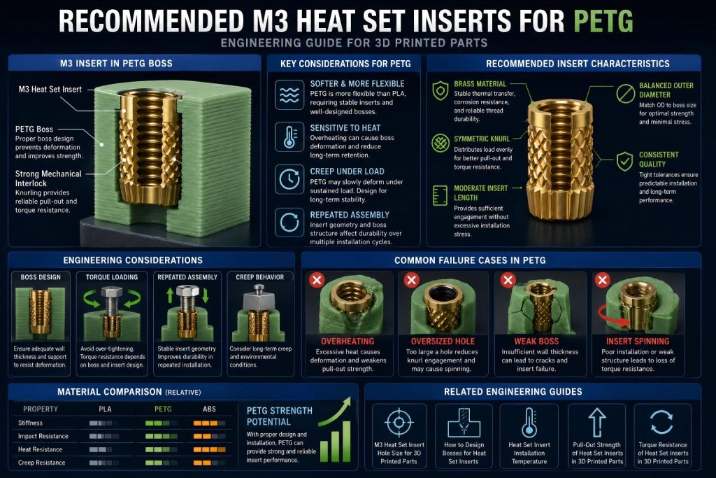
Why PETG Requires Different Insert Considerations
Many insert configurations that work in PLA may perform poorly in PETG if the surrounding structure is not properly designed.
PETG tends to deform more easily under sustained mechanical load and elevated temperatures.
In practical assemblies, this may lead to:
- reduced torque retention
- insert movement over time
- spinning inserts
- boss expansion
- weakening around the insert base
For repeated assembly structures, PETG often benefits from more stable insert geometries and controlled installation conditions.
What Makes a Good M3 Heat Set Insert for PETG
A suitable M3 insert for PETG should prioritize mechanical stability rather than maximum aggressiveness.
Important characteristics include:
- balanced outer diameter
- consistent knurl geometry
- controlled insertion depth
- stable thermal behavior
- good load distribution into the surrounding boss
Very aggressive knurl patterns may increase installation stress and create local deformation in softer PETG structures.
A stable mechanical interlock is usually more important than extreme insertion force.
Recommended Insert Characteristics for PETG
Brass Material
Brass heat set inserts are commonly used because they provide:
- stable thermal transfer
- predictable installation behavior
- good corrosion resistance
- reliable thread durability
Brass also allows more consistent heat distribution during installation compared with some coated or mixed-material inserts.
Symmetric Knurl Geometry
Symmetric knurl structures often perform better in PETG because they distribute load more evenly into the surrounding plastic.
This can improve:
- pull-out resistance
- torque resistance
- long-term stability
- repeated assembly durability
Moderate Insertion Length
Very short inserts may not provide enough engagement area in PETG.
Extremely long inserts may increase stress concentration and overheating risk during installation.
For many functional PETG parts, moderate insertion lengths provide a better balance between retention and structural stability.
Balanced Outer Diameter
Oversized insert diameters may overstress PETG bosses during thermal installation.
Undersized inserts may reduce holding strength.
A balanced OD matched to the boss structure is generally more important than maximizing insert size.
Engineering Considerations for PETG Insert Design
Boss Design
PETG bosses should contain enough surrounding material to resist deformation during both installation and operational loading.
Thin bosses may lead to:
- radial expansion
- cracking near layer lines
- insert loosening over time
Related Guide:
How to Design Bosses for Heat Set Inserts
Repeated Assembly
PETG is frequently used in:
- electronics housings
- robotics panels
- battery enclosures
- service covers
- modular assemblies
These structures often experience repeated screw installation cycles.
A stable insert geometry becomes increasingly important in these applications.
Torque Loading
Because PETG is more flexible than PLA, excessive tightening torque may deform the surrounding boss structure even when the insert itself remains secure.
Torque resistance depends on:
- insert geometry
- boss wall thickness
- layer adhesion
- screw engagement length
Related Guide:
Torque Resistance of Heat Set Inserts in 3D Printed Parts
Long-Term Creep Behavior
PETG may slowly deform under continuous load over time.
This is especially important in:
- warm environments
- vibration-loaded assemblies
- compressed fastening structures
Insert systems designed for long-term stability should account for creep behavior rather than focusing only on initial retention force.
Common PETG Insert Failure Cases
Overheating During Installation
Excessive installation temperature may create oversized melted zones around the insert.
This can weaken long-term retention and reduce pull-out strength.
Related Guide:
Heat Set Insert Installation Temperature for 3D Printed Parts
Oversized Holes
If the hole diameter is too large, PETG may not generate enough mechanical interlock with the insert knurl geometry.
This may lead to spinning inserts or unstable torque behavior.
Related Guide:
M3 Heat Set Insert Hole Size for 3D Printed Parts
Weak Boss Structures
Even a correctly installed insert may fail if the surrounding boss lacks sufficient wall thickness or structural support.
Boss geometry remains one of the primary factors affecting long-term insert stability.
M3 Inserts in PETG Are Part of a Fastening System
A successful PETG insert installation depends on more than choosing an M3 thread size.
Long-term performance is influenced by the interaction between:
- insert geometry
- boss design
- hole size
- installation temperature
- torque loading
- layer adhesion
- repeated assembly cycles
The insert, boss, and printed structure must work together as a complete fastening system.
Related Engineering Guides
- M3 Heat Set Insert Hole Size for 3D Printed Parts
- Heat Set Insert Hole Size Guide
- How to Design Bosses for Heat Set Inserts
- Pull-Out Strength of Heat Set Inserts in 3D Printed Parts
- Torque Resistance of Heat Set Inserts in 3D Printed Parts
- Heat Set Insert Installation Temperature for 3D Printed Parts
Conclusion
PETG requires a more balanced approach to heat set insert design than many standard hobby printing materials.
For M3 heat set inserts, long-term fastening stability depends on selecting insert geometries that match PETG’s thermal behavior, flexibility, and creep characteristics.
In most functional assemblies, stable boss design and controlled installation behavior are more important than maximizing insert aggressiveness alone.
Explore More Engineering References
Explore additional engineering guides, fastening references, insert recommendations, and 3D printed assembly knowledge across the InsertGuide engineering network.
Related Engineering Guides
- How to Choose Heat Set Inserts for 3D Printed Parts
- Heat Set Insert Hole Size Guide
- How to Design Bosses for Heat Set Inserts
- PLA vs PETG vs ABS for Threaded Inserts
- Why Heat Set Inserts Fail in 3D Printed Parts
- Pull-Out Strength of Heat Set Inserts in 3D Printed Parts
- Torque Resistance of Heat Set Inserts in 3D Printed Parts
- Layer Adhesion and Heat Set Insert Strength in 3D Printed Parts
- Heat Set Insert Installation Temperature for 3D Printed Parts
- Screw Engagement Length for Heat Set Inserts in 3D Printed Parts
Related Decision Resources
For insert selection, tool choice, and supplier comparison, use these decision-focused references after the engineering requirements are defined.