
If your M3 heat set inserts are spinning, cracking PLA, or failing to hold inside 3D printed parts, the most common reason is incorrect hole size or tolerance.
This guide explains the recommended M3 hole size for PLA and PETG materials.
When designing threaded fastening structures for 3D printed parts, M3 heat set inserts are one of the most commonly used insert sizes. They appear in electronics enclosures, robotics assemblies, printer frames, fixtures, battery housings, and repeated-service components where printed plastic threads would fail over time.
For most M3 heat set inserts used in 3D printed parts, the recommended starting hole size is typically between 4.0 mm and 4.2 mm.
The exact value depends on:
- insert outer diameter
- knurl geometry
- printing material
- installation temperature
- required pull-out strength
- torque resistance requirements
A correct hole size is not simply about making the insert fit. It directly affects how the insert transfers load into the surrounding printed structure.
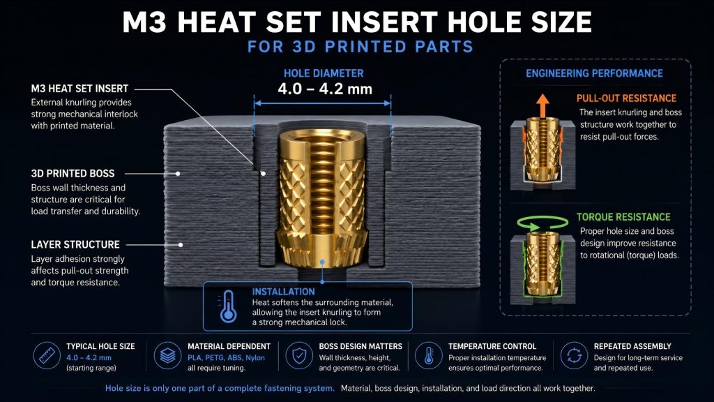
Why M3 Heat Set Insert Hole Size Matters
An M3 insert hole that is too small can create excessive installation stress and damage the surrounding plastic during insertion.
An M3 insert hole that is too large may reduce contact pressure between the insert and the printed material, leading to poor pull-out strength and lower torque resistance.
In real engineering assemblies, M3 inserts are often used in:
- repeated assembly structures
- removable covers
- sensor brackets
- lightweight robotics systems
- electronics housings
- vibration-loaded parts
In these applications, hole size becomes part of the overall fastening system rather than a simple dimensional value.
Typical M3 Heat Set Insert Hole Sizes
| Material | Typical Starting Hole Size |
|---|---|
| PLA | 4.0–4.1 mm |
| PETG | 4.1–4.2 mm |
| ABS | 4.0–4.2 mm |
| Nylon | Depends heavily on shrinkage behavior |
| Carbon Fiber Nylon | Often requires tuning based on fiber content |
These values are starting references only.
Different insert manufacturers use different:
- outer diameters
- knurl depths
- insertion geometries
- thermal expansion behavior
The actual insert datasheet should always be checked before finalizing production dimensions.
Engineering Factors That Affect M3 Insert Hole Size
Boss Wall Thickness
For the next structural step, see M3 boss design.
Hole size alone does not determine insert performance.
The surrounding boss structure must contain enough material to absorb installation heat and distribute operational loads into the printed part.
Thin boss walls can lead to:
- radial cracking
- layer separation
- boss deformation
- reduced service life
Related Guide:
How to Design Bosses for Heat Set Inserts
Layer Adhesion
3D printed parts are anisotropic structures.
If layer adhesion is weak, even a correctly sized M3 insert hole may fail under pull-out loads or repeated tightening cycles.
Layer orientation, print temperature, and cooling settings all influence insert retention strength.
Related Guide:
Layer Adhesion and Heat Set Insert Strength in 3D Printed Parts
Installation Temperature
After selecting the pilot hole, verify the full M3 insert installation process.
Before installing the insert, compare the pilot hole depth with the hole depth chart.
Excessive installation temperature can over-soften the surrounding plastic and weaken the load path around the insert.
Insufficient temperature may prevent proper material flow into the knurl structure.
A stable installation process is often more important than chasing extremely tight dimensional tolerances.
Related Guide:
Heat Set Insert Installation Temperature for 3D Printed Parts
Repeated Assembly and Serviceability
M3 inserts are frequently used in assemblies that require maintenance access.
Examples include:
- electronics covers
- battery compartments
- robotics panels
- modular fixtures
Repeated screw installation cycles increase stress on the surrounding printed structure.
In these cases, proper boss design and controlled installation geometry become more important than minimum hole tolerance alone.
Common M3 Heat Set Insert Failure Cases
Hole Too Small
For tolerance control before installation, use the pilot hole tolerance reference.
Typical results:
- boss cracking
- excessive insertion force
- distorted geometry
- overheated surrounding material
Hole Too Large
Typical results:
- spinning inserts
- reduced pull-out strength
- poor torque resistance
- unstable fastening behavior
Weak Boss Geometry
Even a correct M3 hole size cannot compensate for insufficient surrounding structure.
Weak bosses often fail through:
- layer splitting
- radial expansion
- fatigue around the insert base
Overheating During Installation
Excessive heat may cause:
- material degradation
- oversized melted zones
- weak insert retention
- inconsistent installation depth
M3 Heat Set Inserts as a Fastening System
An M3 insert hole should not be treated as an isolated dimension.
In real engineering assemblies, insert performance depends on the interaction between:
- hole size
- boss geometry
- material behavior
- thermal installation process
- layer adhesion
- load direction
- repeated assembly cycles
A correct hole diameter is only one part of a stable fastening structure.
Related Engineering Guides
- Heat Set Insert Hole Size Guide
- How to Design Bosses for Heat Set Inserts
- Pull-Out Strength of Heat Set Inserts in 3D Printed Parts
- Torque Resistance of Heat Set Inserts in 3D Printed Parts
- Heat Set Insert Installation Temperature for 3D Printed Parts
- Layer Adhesion and Heat Set Insert Strength in 3D Printed Parts
Conclusion
For most M3 heat set inserts used in 3D printed parts, a starting hole size between 4.0 mm and 4.2 mm is commonly used.
However, successful insert installation depends on more than dimensional fit.
The final performance of an M3 insert is determined by the complete fastening structure, including boss design, material behavior, installation conditions, and long-term service loading.
FAQ
What is the correct hole size for M3 heat set inserts in 3D printed parts?
✔ Answer:
For most M3 heat set inserts, the recommended hole size is typically 4.0 mm to 4.2 mm, depending on material type such as PLA or PETG and the insert’s knurl design.
If the hole is too large, the insert may spin and lose torque resistance. If the hole is too small, it can cause cracking in PLA during installation. Inconsistent hole sizing can also lead to weak retention or premature failure under load.
Does PETG require a different M3 insert hole size than PLA?
Yes. PETG often benefits from a slightly larger starting hole size because of its thermal behavior and material flexibility during insert installation.
Can an M3 insert hole be too large?
Yes. An oversized hole may reduce pull-out strength and torque resistance, causing the insert to spin or loosen during repeated assembly.
Does boss design affect M3 insert performance?
Yes. Boss wall thickness and surrounding structure strongly affect load distribution, insert retention, and long-term durability.
Related Engineering Guides
- How to Choose Heat Set Inserts for 3D Printed Parts
- Heat Set Insert Hole Size Guide
- How to Design Bosses for Heat Set Inserts
- PLA vs PETG vs ABS for Threaded Inserts
- Why Heat Set Inserts Fail in 3D Printed Parts
- Pull-Out Strength of Heat Set Inserts in 3D Printed Parts
- Torque Resistance of Heat Set Inserts in 3D Printed Parts
- Layer Adhesion and Heat Set Insert Strength in 3D Printed Parts
- Heat Set Insert Installation Temperature for 3D Printed Parts
- Screw Engagement Length for Heat Set Inserts in 3D Printed Parts
Related Decision Resources
For insert selection, tool choice, and supplier comparison, use these decision-focused references after the engineering requirements are defined.