
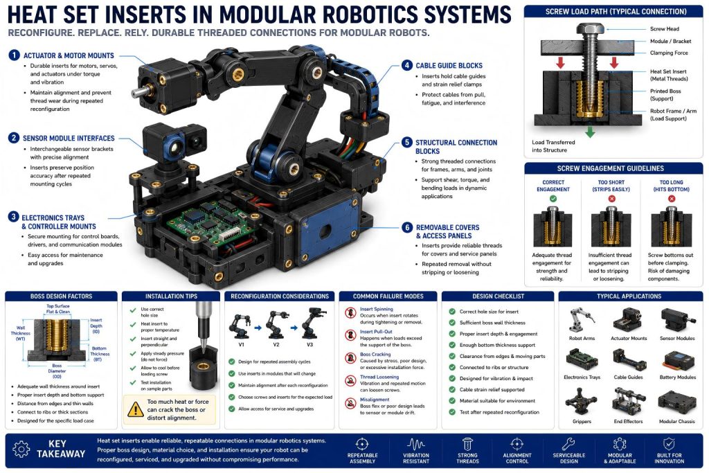
Heat set inserts in modular robotics systems are used to create durable threaded points for interchangeable arms, sensor modules, electronics trays, actuator brackets, cable guides, protective covers, and structural connection blocks. In 3D printed modular robots, inserts help printed parts survive repeated reconfiguration, maintenance, vibration, and screw assembly without wearing out plastic threads.
Modular robotics systems are not single static parts. They are assemblies that change. A sensor may be replaced. A bracket may move. An actuator mount may be redesigned. A cable guide may be repositioned. A robot arm module may be removed for service.
In this type of system, fastening points must survive more than one assembly cycle.
The key point is:
Heat set inserts in modular robotics systems should support repeated reconfiguration while keeping mechanical alignment, vibration resistance, and service access reliable.
Why Modular Robotics Systems Use Heat Set Inserts
Robotics systems often combine structure, motion, electronics, sensors, cables, and serviceable modules. When these systems are 3D printed, threaded connections become especially important because many parts need to be removed, adjusted, upgraded, or replaced.
Common modular robotics applications include:
- interchangeable sensor modules
- robot arm brackets
- actuator mounting blocks
- servo motor brackets
- electronics trays
- controller housings
- cable guide blocks
- battery modules
- gripper components
- removable covers
- joint protection plates
- experimental end effectors
- modular chassis sections
- inspection or camera modules
Printed plastic threads may work for early prototypes, but modular robotics systems usually require repeated screw use. Screws are removed during testing, calibration, tuning, repair, and redesign.
Heat set inserts improve:
- repeated assembly
- durable threaded connections
- modular part replacement
- actuator bracket serviceability
- sensor module adjustment
- electronics tray maintenance
- cable guide reconfiguration
- stronger screw retention
- better long-term reliability
In modular robotics, heat set inserts do not only make threads stronger. They help the robot remain rebuildable.
Common Insert Locations in Modular Robots
Heat set inserts are usually placed where a module needs to be fastened, removed, adjusted, or replaced.
Actuator and Motor Mounts
Actuator mounts carry mechanical loads from motors, servos, linear actuators, belts, gears, or linkages. These inserts may experience torque, vibration, and repeated tightening.
A motor mount insert should not be placed in a thin unsupported wall. The boss should connect to the bracket body, ribs, or a reinforced mounting block.
If the actuator shifts, the robot may lose motion accuracy. Insert reliability directly affects mechanical performance.
Sensor Module Interfaces
Robots often use cameras, lidar units, IMUs, proximity sensors, encoders, switches, and inspection probes.
Heat set inserts allow sensor modules to be swapped or adjusted without damaging the printed bracket. But the insert must preserve alignment. A tilted insert or distorted boss can change sensor angle or position.
Sensor module inserts should be designed for accuracy, not just strength.
Electronics Trays and Controller Housings
Robotics systems usually include control boards, drivers, power distribution boards, communication modules, and wiring.
Electronics trays may need frequent access during testing and repair. Inserts provide durable threads for board mounts, covers, cable clamps, and removable electronics plates.
These insert locations usually carry lower force, but serviceability and alignment still matter.
Cable Guide Blocks
Cables move through robotics systems like nerves through a mechanical animal. If they are unsupported, they can snag, fatigue, pull on connectors, or interfere with joints.
Heat set inserts can hold cable guide blocks, strain relief clamps, wire covers, and routing brackets. These features may be repositioned as the robot design changes.
Cable guide inserts should be connected to the structure so cable loads do not crack thin tabs.
Structural Connection Blocks
Modular robots often use printed blocks or plates to connect arms, frames, joints, rails, or accessory modules.
These inserts may experience shear, torque, bending, and repeated assembly. They need stronger boss geometry than simple cover screws.
Structural connection inserts should be placed in thick, supported regions with clear load paths.
Removable Covers and Access Panels
Robotics systems often require access panels for electronics, belts, gears, batteries, connectors, or sensors. Heat set inserts make these covers more serviceable.
Cover inserts should be strong enough for repeated removal, but they should not be confused with structural load-bearing inserts.
A cover screw should close the robot. A structural screw should carry the load. Those jobs deserve different boss designs.
Reconfiguration Is the Main Design Challenge
Modular robotics systems are built to change. That is their strength, but it also creates fastening problems.
A robot may go through many versions:
- sensor position changes
- actuator upgrades
- gripper replacement
- cable routing changes
- battery relocation
- electronics tray redesign
- arm length modification
- test fixture adaptation
- field repair
- prototype-to-production refinement
Each change may require screws to be removed and installed again. Printed plastic threads can degrade quickly under this behavior.
Heat set inserts are useful because they allow the printed structure to survive repeated module changes.
However, reconfiguration also means that inserts may be used in ways the first design did not expect. For example, a bracket originally used for a light sensor may later hold a heavier camera module. A cable guide may later carry a larger harness. An electronics tray may later support an additional board.
This is why critical insert locations should include reasonable design margin.
Modular robots evolve. Their screws remember every version.
Load Paths in Modular Robotics Assemblies
A modular robot is a network of load paths.
A screw may connect a sensor bracket to a frame, a motor mount to an arm, a cover to a housing, or a cable guide to a moving joint. Each connection transfers force into the printed structure.
Good insert design considers:
- where the screw force enters the part
- whether the insert is loaded in tension, shear, or torque
- whether the module creates bending load
- whether vibration will loosen the joint
- whether the boss connects to ribs or thick walls
- whether the part will be removed often
- whether the load direction changes during robot motion
A heat set insert should not be treated as an isolated metal nut inside plastic. It should be part of a supported load path.
For structural connection blocks and actuator brackets, pull-out strength should be evaluated as part of the supported load path through the printed module.
For structural modules, the boss should connect to the main body through ribs, gussets, thickened pads, or reinforced blocks. For light covers, a simpler boss may be enough. For sensors, alignment matters more than brute force.
Different robotic modules need different insert strategies.
Boss Design for Modular Robotics Inserts
Boss design should match the function of the insert. For modular robotics systems, boss design should be matched to the insert’s job, because actuator mounts, sensor brackets, cable guides, covers, and structural connectors do not carry the same load.
Important boss design factors include:
- wall thickness around the insert
- outer boss diameter
- insert depth
- bottom material thickness
- distance from edges
- screw engagement length
- nearby ribs or gussets
- clearance for moving parts
- clearance for wires and connectors
- access for the insertion tool
- expected reconfiguration frequency
- vibration and impact exposure
A motor mount boss needs more strength than a cover boss. A sensor boss needs more alignment control than a cable clamp boss. A structural connector boss needs stronger load transfer than a decorative panel boss.
The mistake is using one insert rule everywhere.
In modular robotics systems, each insert should be assigned a job. Then the boss should be designed for that job.
Screw Engagement and Service Cycles
Screw engagement is important because modular robots are opened, adjusted, and rebuilt often.
In reconfigurable robot modules, screw engagement length should be long enough to survive repeated service cycles without bottoming out, loosening, or interfering with nearby moving parts.
If engagement is too short, screws can loosen, strip, or fail to clamp modules consistently. If screws are too long, they may bottom out below the insert, hit internal components, interfere with moving parts, or create false clamping.
For modular robotics systems, screw length should consider:
- insert length
- module thickness
- washer or spacer thickness
- cover or bracket thickness
- expected service cycles
- vibration
- moving part clearance
- internal electronics clearance
- cable routing clearance
A good modular system makes correct assembly easy. If every screw length is a guessing game, the robot becomes a puzzle box with teeth.
Using consistent screw sizes where possible can reduce assembly errors, but critical structural locations may need longer inserts, deeper bosses, or stronger screw engagement than light covers.
Material Choice for Modular Robotics Systems
Material choice affects stiffness, toughness, vibration behavior, heat resistance, and insert installation.
PLA
PLA can work for early robotic prototypes, static brackets, low-load covers, and concept models. It prints accurately and is easy to use.
However, PLA is not ideal for high-vibration, impact-prone, warm, or repeatedly serviced robot parts. It may crack around thin bosses or soften near motors and electronics.
PETG
PETG is tougher than PLA and can work for moderate-duty robot brackets, covers, cable guides, and electronics trays.
It can flex more under load, so structural modules and sensor brackets may need ribs or thicker sections.
ABS and ASA
ABS and ASA offer better heat resistance and can be useful for robot covers, housings, brackets, and serviceable modules.
They require good print quality and layer adhesion. Warping can affect alignment and module fit.
Nylon and Carbon Fiber Nylon
Nylon and carbon fiber nylon are strong candidates for functional robotics components. They can provide toughness, wear resistance, and better performance in moving assemblies.
Carbon fiber nylon can improve stiffness and dimensional stability, which is useful for actuator mounts, sensor brackets, and structural connection blocks. Insert installation must still be controlled, and boss geometry remains critical.
Material selection should match the module’s job, not the robot’s overall ambition.
Vibration, Motion, and Insert Reliability
Robotics systems create motion. Motion creates vibration, cable movement, repeated loads, and sometimes impact.
For actuator mounts, structural connectors, and frequently adjusted modules, torque resistance helps prevent inserts from rotating during repeated tightening or vibration.
Insert locations should be checked for:
- screw loosening under vibration
- insert spinning under repeated tightening
- pull-out under module load
- boss cracking during impact
- bracket flex during motion
- cable pull near moving joints
- layer separation around structural connectors
- sensor alignment drift
A robot may test an insert in multiple directions during operation. A static bracket might only see one load direction, but a moving robot may load the same connection through acceleration, deceleration, vibration, and shock.
For high-motion modules, the insert boss should be connected to a real structure. Thin walls, isolated tabs, and unsupported towers are weak little castles, and robots are not kind to castles.
Cable Management and Service Access
Robotics systems are full of cables. Motors, encoders, sensors, batteries, controllers, and communication modules all need wires.
Cable management inserts can support:
- strain relief brackets
- cable guide blocks
- removable wire covers
- harness routing clamps
- connector retention plates
- flexible cable chain mounts
These insert points are not always high-load, but they are important. A loose cable can cause motion problems, connector stress, or service confusion.
Good cable insert design should:
- separate cable loads from sensor alignment
- avoid sharp bends near connectors
- allow easy service access
- support repeated cable repositioning
- keep wires clear of moving joints
- connect cable clamps to reinforced areas
A modular robot should be easy to service without turning every cable into a tiny escape artist.
Common Failure Modes in Modular Robotics Inserts
Heat set inserts in modular robotics systems fail through repeated use, vibration, load changes, and poor module-specific design.
Insert Spinning
Insert spinning happens when the insert rotates inside the plastic during screw tightening or removal.
Common causes include:
- oversized holes
- overheated installation
- thin boss walls
- excessive screw torque
- repeated reconfiguration
- weak support around the insert
This is common when a module is adjusted frequently.
Insert Pull-Out
Pull-out occurs when the insert is pulled out of the printed part under tension, impact, or module load.
Common causes include:
- shallow insert depth
- weak bottom material
- unsupported boss geometry
- high load from actuators or brackets
- poor layer orientation
- module weight increasing after redesign
Structural connection blocks and motor mounts need special attention.
Boss Cracking
Boss cracking can occur during installation, assembly, or impact.
Typical causes include:
- undersized holes
- brittle material
- insert too close to an edge
- insufficient wall thickness
- overtightened screws
- poor installation temperature
- repeated screw cycling
For small bosses, actuator brackets, and alignment-critical modules, installation temperature should be controlled so inserts seat cleanly without cracking the boss or deforming the module geometry.
Sensor Misalignment
A sensor may shift because the insert tilts, the bracket flexes, or the boss deforms. This can affect robot perception, feedback, and calibration.
Cable Clamp Failure
Cable guide inserts may loosen if cable movement repeatedly pulls on thin unsupported tabs.
Thread Loosening
Repeated motion and vibration can loosen screws if engagement is too short, clamping support is poor, or the printed structure creeps.
Module Fit Drift
After many reconfigurations, modules may no longer sit square if inserts loosen, bosses deform, or mating surfaces wear.
This failure can be sneaky because nothing looks broken at first. The robot simply becomes less precise.
Design Checklist for Modular Robotics Systems
Before using heat set inserts in modular robotics systems, check the following:
- Is the insert used for an actuator, sensor, electronics tray, cable guide, cover, or structural connector?
- Does the boss match the load and service function?
- Is the wall thickness around the insert sufficient?
- Is there enough material below the insert?
- Is the insert far enough from edges and moving parts?
- Is screw engagement length sufficient?
- Will the screw bottom out or hit internal components?
- Can the insert be installed straight?(For repeatable module assembly, correct hole size helps inserts seat straight and consistently across printed actuator mounts, sensor plates, electronics trays, and cable guide blocks.)
- Will installation heat distort alignment-critical features?
- Is the boss connected to ribs, gussets, or the main body?
- Will the module be reconfigured often?
- Will vibration or impact affect the insert?
- Are cable loads separated from sensor alignment points?
- Does the material match the module environment?
- Does print orientation support pull-out and torque loads?
- Has the design been tested after repeated module swaps?
A modular robot should be tested as a living assembly, not as a collection of pretty printed objects.
Engineering Takeaway
Heat set inserts can make 3D printed modular robotics systems more durable, serviceable, and adaptable. They are especially useful for actuator mounts, sensor modules, electronics trays, cable guides, structural connection blocks, removable covers, and experimental end effectors.
But modular robotics puts special pressure on fastening design because the system changes over time.
Reliable insert performance depends on:
- correct hole size
- controlled installation
- module-specific boss geometry
- sufficient screw engagement
- supported load paths
- vibration resistance
- cable strain relief
- material choice
- print orientation
- repeatable service access
- protection of alignment-critical modules
A good modular robot does not only assemble once.
It can be opened, repaired, upgraded, reconfigured, and tested again without destroying its own fastening points.
Heat set inserts provide durable threads, but the printed structure must give those threads a reliable mechanical home.
FAQ
Are heat set inserts useful in modular robotics systems?
Yes. Heat set inserts are useful in modular robotics systems because they provide durable metal threads for actuator mounts, sensor modules, electronics trays, cable guides, removable covers, structural blocks, and reconfigurable robot components.
Where should heat set inserts be used in modular robots?
They should be used in repeated-service areas such as motor brackets, servo mounts, sensor plates, controller housings, cable clamps, battery modules, gripper parts, and structural connection blocks.
What causes inserts to fail in modular robotics parts?
Common causes include thin boss walls, oversized or undersized holes, poor installation temperature, short screw engagement, repeated reconfiguration, vibration, cable pull, poor layer orientation, and unsupported load paths.
Do modular robotics inserts need different boss designs?
Yes. Motor mounts, sensor brackets, electronics trays, cable guides, covers, and structural connectors carry different loads. Each insert boss should be designed for its specific function instead of using one generic boss everywhere.
What material is best for 3D printed modular robotics parts with inserts?
PLA can work for early prototypes, PETG for moderate-duty parts, ABS or ASA for better heat resistance, and nylon or carbon fiber nylon for stronger functional robotics components. Material choice should match load, vibration, service cycles, and alignment requirements.
Related Engineering Guides
- How to Choose Heat Set Inserts for 3D Printed Parts
- Heat Set Insert Hole Size Guide
- How to Design Bosses for Heat Set Inserts
- PLA vs PETG vs ABS for Threaded Inserts
- Why Heat Set Inserts Fail in 3D Printed Parts
- Pull-Out Strength of Heat Set Inserts in 3D Printed Parts
- Torque Resistance of Heat Set Inserts in 3D Printed Parts
- Layer Adhesion and Heat Set Insert Strength in 3D Printed Parts
- Heat Set Insert Installation Temperature for 3D Printed Parts
- Screw Engagement Length for Heat Set Inserts in 3D Printed Parts