
M3 heat set insert boss design directly affects pull-out strength, torque resistance, layer adhesion behavior, and long-term fastening stability in 3D printed parts.
A correct hole size alone is not enough.
The boss functions as the primary load-bearing structure around the insert and directly affects pull-out strength, torque resistance, long-term durability, and repeated assembly stability.
For M3 heat set inserts used in 3D printed parts, boss design must balance:
- wall thickness
- insert diameter
- layer adhesion
- installation temperature
- load direction
- material behavior
Poor boss geometry is one of the most common causes of insert failure in functional printed assemblies.
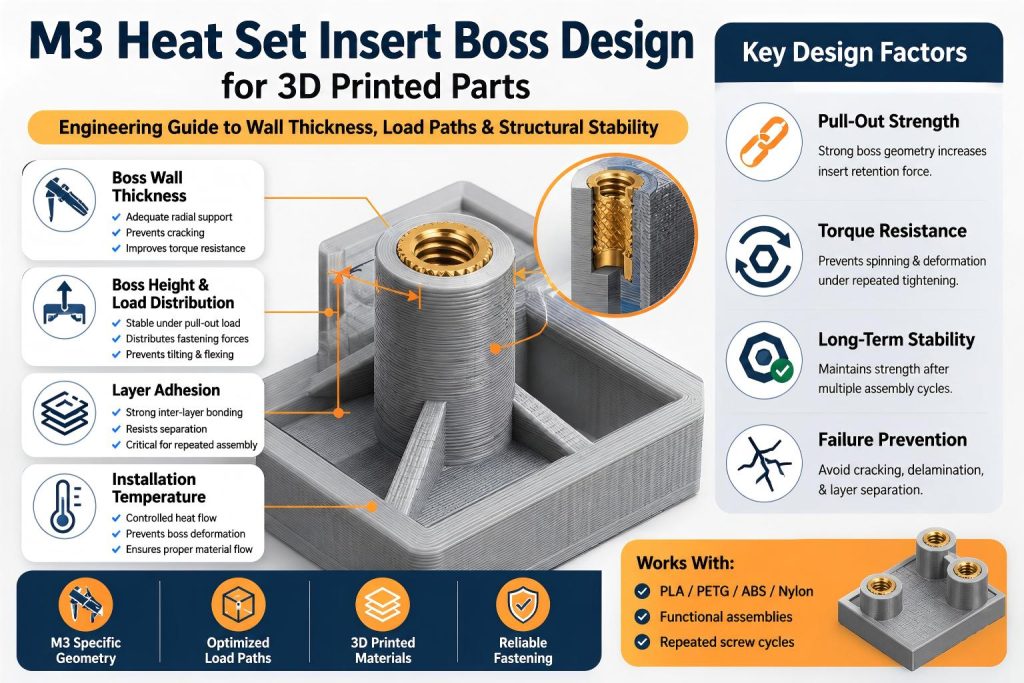
Why Boss Design Matters for M3 Inserts
The boss transfers fastening loads from the insert into the surrounding printed structure.
If the boss is too thin, too short, or poorly supported, the insert may fail even if the installation process appears correct.
Common failure modes include:
- radial cracking
- boss expansion
- insert spinning
- layer separation
- pull-out failure
- deformation during repeated assembly
In many cases, boss geometry has a greater effect on long-term fastening performance than insert size itself.
M3 Heat Set Insert Boss Design Considerations
Boss geometry should also be checked against M3 pull-out strength requirements.
Boss support is also part of M3 insert installation quality.
Boss support also affects M3 insert torque resistance.
For supporting boss geometry, see the boss OD ratio reference.
M3 heat set insert boss design considerations include wall thickness, boss height, load distribution, layer adhesion, installation temperature, and repeated assembly stability.
Recommended Boss Structure for M3 Heat Set Inserts
For most M3 insert applications, the boss should provide enough surrounding material to absorb thermal installation stress and operational loads.
A stable boss structure generally includes:
- adequate wall thickness
- gradual load transfer into surrounding geometry
- support near the insert base
- sufficient height for load distribution
- controlled hole dimensions
Very thin bosses may initially hold the insert but often fail after repeated tightening cycles or vibration exposure.
Boss Wall Thickness Considerations
Boss wall thickness strongly affects structural durability.
If the wall is too thin, the insert may create excessive radial stress during installation.
This becomes especially important in materials such as:
- PETG
- ABS
- nylon
- carbon fiber filled polymers
These materials behave differently under heat and compression compared with PLA.
Thin boss walls may lead to:
- cracking near layer lines
- local deformation
- reduced torque resistance
- lower pull-out strength
A balanced boss diameter is usually more reliable than aggressively minimizing part size.
Boss Height and Load Distribution
Boss height affects how fastening loads spread into the surrounding printed structure.
Very short bosses may concentrate stress near the insert opening.
Taller bosses can improve:
- load distribution
- insert stability
- repeated assembly durability
- resistance to tilting forces
However, excessively tall unsupported bosses may become flexible and unstable under vibration or side loading.
Boss geometry should match the expected operational load path rather than following a universal dimension rule.
Layer Adhesion and Boss Strength
3D printed bosses are anisotropic structures.
Weak layer adhesion may significantly reduce boss durability even when dimensions appear correct.
Boss failure often follows layer boundaries under:
- pull-out loads
- overtightening
- vibration
- repeated assembly cycles
Layer orientation, print temperature, and cooling settings all influence boss performance around M3 inserts.
Related Guide:
Layer Adhesion and Heat Set Insert Strength in 3D Printed Parts
Installation Temperature and Boss Stability
Heat set insert installation creates thermal stress inside the boss structure.
Excessive installation temperature may soften too much surrounding material and weaken structural integrity.
Insufficient temperature may prevent proper material flow into the insert knurl geometry.
Bosses designed with insufficient wall thickness are especially vulnerable to overheating damage during insert installation.
Related Guide:
Heat Set Insert Installation Temperature for 3D Printed Parts
Repeated Assembly Behavior
Many M3 inserts are used in assemblies that require maintenance access or repeated disassembly.
Examples include:
- electronics enclosures
- battery covers
- robotics panels
- modular fixtures
- removable service components
Repeated screw installation cycles gradually increase stress around the boss structure.
Stable boss geometry becomes critical for maintaining long-term fastening reliability.
Common M3 Boss Design Failure Cases
Boss Too Thin
Use the minimum wall thickness reference when checking whether the boss has enough plastic support.
Typical results include:
- cracking during installation
- insert loosening
- reduced pull-out strength
- deformation under torque load
Unsupported Boss Structures
Tall unsupported bosses may flex during tightening and eventually fail through fatigue or layer separation.
Poor Load Path Design
Bosses positioned near unsupported walls or thin surrounding geometry may fail even when insert dimensions appear correct.
The surrounding structure must help distribute operational loads away from the insert itself.
Weak Layer Adhesion
Weak print bonding often causes failure near the insert base during pull-out loading or repeated assembly cycles.
M3 Boss Design Is Part of a Fastening System
An M3 insert boss should not be treated as a simple cylindrical feature.
Successful fastening structures depend on the interaction between:
- boss geometry
- hole size
- insert design
- layer adhesion
- installation temperature
- material behavior
- operational loading conditions
The insert and boss must function together as a complete engineering fastening system.
Related Engineering Guides
- M3 Heat Set Insert Hole Size for 3D Printed Parts
- Heat Set Insert Hole Size Guide
- How to Design Bosses for Heat Set Inserts
- Pull-Out Strength of Heat Set Inserts in 3D Printed Parts
- Torque Resistance of Heat Set Inserts in 3D Printed Parts
- Layer Adhesion and Heat Set Insert Strength in 3D Printed Parts
- Heat Set Insert Installation Temperature for 3D Printed Parts
Conclusion
Boss geometry is one of the most important factors affecting M3 heat set insert performance in 3D printed assemblies.
A correctly designed boss improves load distribution, pull-out strength, torque resistance, and long-term fastening durability.
In functional engineering assemblies, successful insert performance depends on treating the boss, insert, and surrounding structure as a complete integrated fastening system.
Related Engineering Guides
- How to Choose Heat Set Inserts for 3D Printed Parts
- Heat Set Insert Hole Size Guide
- How to Design Bosses for Heat Set Inserts
- PLA vs PETG vs ABS for Threaded Inserts
- Why Heat Set Inserts Fail in 3D Printed Parts
- Pull-Out Strength of Heat Set Inserts in 3D Printed Parts
- Torque Resistance of Heat Set Inserts in 3D Printed Parts
- Layer Adhesion and Heat Set Insert Strength in 3D Printed Parts
- Heat Set Insert Installation Temperature for 3D Printed Parts
- Screw Engagement Length for Heat Set Inserts in 3D Printed Parts
Related Decision Resources
For insert selection, tool choice, and supplier comparison, use these decision-focused references after the engineering requirements are defined.