
Heat set inserts for electronics enclosure lid cycling are used when a 3D printed electronics housing needs a removable cover, service panel, access lid, sensor cover, battery door, or inspection plate that may be opened and closed many times.
This application is different from a one-time assembly. In lid cycling, the insert joint must survive repeated screw removal, repeated tightening, changing preload, local boss stress, and long-term material behavior. The design goal is not only to make the screw hold once, but to keep the fastening structure reliable after multiple service cycles.
For a broader electronics fastening context, see Heat Set Inserts in Electronics Mounting Systems.
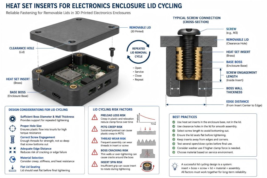
Why Lid Cycling Is a Specific Insert Design Problem
Electronics enclosures often need removable lids. A cover may be opened to access a battery, replace a board, adjust a sensor, inspect wiring, update a module, or repair a component. This repeated opening and closing creates a different load pattern than a permanent assembly.
In a static assembly, the screw may be tightened once and left alone. In lid cycling, the same insert may experience:
- repeated screw insertion and removal
- changing screw preload
- small alignment errors during reassembly
- local boss compression
- thread wear from frequent handling
- creep in PETG or other ductile materials
- edge stress if the lid screw is close to a wall or corner
This makes electronics enclosure lid cycling a useful application case for understanding how insert geometry, boss design, screw engagement, and printed material work together.
Typical Lid Cycling Use Cases
Heat set inserts are commonly used in 3D printed electronics enclosures where screws need to be removed without damaging the plastic thread. Common examples include:
- sensor housings with removable covers
- battery compartments
- controller boxes
- PCB enclosures
- small robotics electronics modules
- IoT device housings
- test equipment cases
- prototype electronics boxes
- service panels for wiring access
In these cases, the insert is not just a thread. It becomes part of a small serviceable fastening structure.
Main Failure Modes in Lid Cycling
Insert Loosening Over Time
An insert may feel tight after the first assembly but become loose after repeated lid removal. This can happen when the printed hole is too large, the surrounding plastic relaxes, the insert knurls do not have enough grip, or the screw preload drops over time.
See also: Why Do Heat Set Inserts Become Loose Over Time?
Preload Drop After Reassembly
When a lid is repeatedly tightened, the screw does not always return to the same clamp force. Plastic compression, material creep, screw length variation, and small seating changes can reduce the effective preload.
See also: Why Does Screw Preload Drop in 3D Printed Insert Joints?
Boss Cracking Around the Insert
A thin boss may crack during installation or after repeated tightening. This risk increases when the hole is too small, the insert is overheated, the wall thickness is too low, or the lid screw is close to a corner.
See also: Why Do Bosses Crack Around Heat Set Inserts?
Insert Spin During Screw Tightening
If the insert does not have enough torque resistance, the insert may rotate when the lid screw is tightened. This is common when the printed hole is too large, the insert is installed too cold, or the plastic does not flow into the knurl pattern.
See also: Why Do Heat Set Inserts Spin in 3D Printed Parts?
Edge or Corner Failure
Electronics enclosures often place lid screws near corners. If the insert is too close to the edge, the plastic wall may split, deform, or lose support during repeated tightening.
See also: Why Do Heat Set Inserts Fail Near Edges or Corners?
Design Variables for Electronics Enclosure Lid Cycling
A reliable lid cycling design should consider the complete fastening structure, not only the insert size.
| Design Variable | Why It Matters in Lid Cycling |
|---|---|
| Insert size | Affects available thread engagement, pull-out resistance, and torque resistance. |
| Hole size | Controls insertion fit, plastic flow, boss stress, and insert grip. |
| Boss diameter | Determines how much plastic supports the insert during repeated tightening. |
| Boss depth | Prevents insert bottoming, proud inserts, and weak axial support. |
| Screw engagement length | Controls thread contact and clamp stability without bottoming out. |
| Lid thickness | Affects screw length selection and clamp force distribution. |
| Material | PLA, PETG, ABS, and nylon respond differently to heat, preload, and repeated assembly. |
| Edge distance | Reduces the risk of wall splitting or corner deformation. |
| Installation temperature | Affects plastic flow around the insert and long-term retention. |
For general hole design rules, see the Heat Set Insert Hole Size Guide. For boss geometry, see How to Design Bosses for Heat Set Inserts.
Recommended Fastening Structure
For electronics enclosure lid cycling, the insert should usually be placed in the enclosure base, while the lid has a clearance hole for the screw. This allows the screw to clamp the lid down into the base without cutting threads into the printed lid material.
A typical structure includes:
- a heat set insert installed in the base boss
- a clearance hole in the removable lid
- enough boss depth for the full insert length
- controlled screw engagement inside the insert
- sufficient edge distance around each boss
- a lid surface that seats evenly before full screw tightening
The lid should not rely on the screw to force a warped cover flat. If the lid is bent, warped, or misaligned, the insert joint may be overloaded during tightening.
Hole Size and Insert Fit
Hole size is one of the most important design choices for repeated lid cycling. If the hole is too large, the insert may not develop enough torque resistance. If the hole is too small, the insert can crack the boss or deform the enclosure wall during installation.
Small electronics enclosures often use thin walls and compact bosses, which makes hole tolerance more important. A test coupon should be printed before finalizing the enclosure if the insert size, material, or printer profile has not been tested before.
For hole-related failure diagnosis, see Why Do Heat Set Inserts Fail When the Hole Is Too Large? and Why Do Heat Set Inserts Fail When the Hole Is Too Small?.
Screw Engagement and Screw Length
In a removable electronics lid, screw length must be selected carefully. The screw should engage enough thread inside the insert to provide stable clamping, but it should not bottom out inside the insert or below the boss.
A screw that is too short may produce weak clamp force. A screw that is too long may create false tightening resistance or push against the bottom of the insert cavity.
For repeated lid cycling, screw engagement should be checked together with:
- lid thickness
- washer thickness, if used
- insert thread depth
- boss depth
- clearance below the insert
- expected number of service cycles
For a deeper reference, see Screw Engagement Length for Heat Set Inserts in 3D Printed Parts.
Material Behavior in Lid Cycling
Material choice affects long-term reliability. PLA is stiff and dimensionally stable, but it may crack around tight inserts or thin bosses. PETG is tougher, but it may creep under sustained screw preload. ABS can tolerate installation heat better than PLA, but still requires good boss geometry. Nylon and carbon fiber nylon may offer toughness, but moisture behavior and printed tolerance should be considered.
For lids that are opened frequently, PETG and other ductile materials should be checked for preload relaxation over time. If the lid must remain sealed or vibration-resistant, screw preload loss may matter more than initial insert strength.
For material comparison, see PLA vs PETG vs ABS for Threaded Inserts.
Repeated Assembly Design Checks
Before using heat set inserts in an electronics enclosure with a removable lid, check the following:
- Confirm the insert size and manufacturer dimensions.
- Check printed hole size against actual printed tolerance.
- Make the boss large enough to support repeated tightening.
- Keep inserts away from thin edges and sharp corners.
- Use a clearance hole in the lid, not a tight screw hole.
- Confirm screw length before tightening the final assembly.
- Check whether the lid seats flat before the screw is tightened.
- Avoid using screw force to correct warped lids.
- Print a test coupon for the insert and material combination.
- Test several lid removal and reassembly cycles before relying on the design.
For a broader repeated assembly explanation, see Heat Set Inserts for Repeated Assembly in 3D Printed Parts.
When Heat Set Inserts Are a Good Fit
Heat set inserts are a good fit for electronics enclosure lid cycling when the design needs:
- repeated opening and closing
- better thread durability than printed plastic threads
- controlled screw engagement
- repairable or serviceable covers
- stable alignment between lid and base
- stronger fastening in compact printed structures
They are especially useful when the lid may be removed during prototyping, testing, battery replacement, sensor adjustment, or field service.
When the Design Needs More Caution
Heat set inserts need more caution when:
- the enclosure wall is very thin
- the insert is close to the edge
- the lid is warped or under bending stress
- the screw is frequently removed
- the part is printed in PETG and held under preload
- the enclosure is exposed to vibration or heat
- the boss is shallow or unsupported
If the enclosure is used in a vibrating electronics assembly, see Why Do Heat Set Inserts Fail Under Vibration?.
Practical Summary
Heat set inserts for electronics enclosure lid cycling should be designed as part of a repeated-service fastening structure. The insert, screw, boss, lid clearance hole, printed material, edge distance, and screw engagement length all affect reliability.
A good design should allow the lid to be removed and reinstalled without damaging the insert joint, cracking the boss, losing preload too quickly, or allowing the insert to spin.
For lid cycling, the most important design question is not simply whether the insert holds once. The real question is whether the joint remains stable after repeated opening, tightening, and service handling.
FAQ
Are heat set inserts useful for removable electronics enclosure lids?
Yes. Heat set inserts are useful when an electronics enclosure lid needs to be removed and reinstalled many times. They provide more durable metal threads than printed plastic threads.
Should the insert be installed in the lid or the base?
In most removable lid designs, the insert is installed in the enclosure base, while the lid uses a clearance hole. This allows the screw to clamp the lid into the base without forming threads in the lid itself.
Why do inserts become loose after repeated lid removal?
Inserts may become loose because of oversized holes, low plastic flow into the knurl pattern, PETG creep, preload relaxation, weak boss geometry, or excessive screw torque during repeated assembly.
What causes boss cracking in electronics enclosures?
Boss cracking can be caused by a hole that is too small, overheated installation, thin boss walls, poor edge distance, brittle material behavior, or excessive screw tightening force.
Do PETG electronics enclosures need special care?
Yes. PETG can be useful for electronics enclosures, but it may creep under long-term screw preload. Repeated lid cycling should be tested if the enclosure must stay tightly clamped over time.
Should I test lid cycling before final use?
Yes. A simple test with repeated screw removal and reassembly can reveal insert spin, boss cracking, preload loss, screw bottoming, and lid fit problems before the design is used in a final enclosure.
Related Guides
- Heat Set Inserts in Electronics Mounting Systems
- Heat Set Inserts for Repeated Assembly in 3D Printed Parts
- Heat Set Insert Hole Size Guide
- How to Design Bosses for Heat Set Inserts
- Screw Engagement Length for Heat Set Inserts in 3D Printed Parts
- Why Do Heat Set Inserts Become Loose Over Time?
- Why Does Screw Preload Drop in 3D Printed Insert Joints?
- Why Do Heat Set Inserts Fail in PETG Parts?