
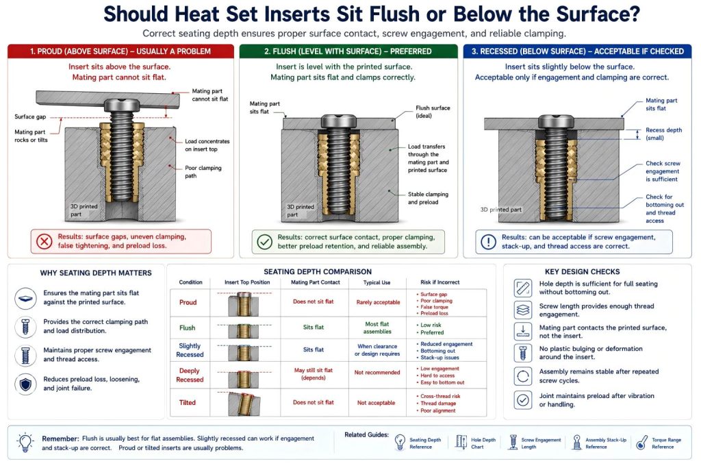
Should heat set inserts sit flush or below the surface? In most 3D printed assemblies, heat set inserts should sit flush with the printed surface when another part needs to clamp flat against that surface. A slightly recessed insert may be acceptable in some designs, but only if screw engagement, thread access, and clamping behavior remain correct.
A heat set insert should usually not sit proud above the printed surface. A proud insert can prevent the mating part from sitting flat, create a surface gap, concentrate load around the insert, and reduce the reliability of the joint.
The correct seating condition depends on the assembly purpose. A flat cover, service panel, bracket, or fixture plate usually needs flush seating. A recessed insert may work when the screw can still engage enough thread and the mating part contacts the printed surface properly.
Short Answer
Use flush seating when the printed part needs a flat mating surface. Slightly below the surface may be acceptable if screw engagement and clamping are still correct. Avoid proud inserts unless the design specifically provides clearance for the insert top.
Why Flush Seating Is Usually Preferred
Flush seating means the top of the heat set insert is level with the printed surface. This is usually preferred because it allows the mating part, lid, bracket, cover, or panel to sit flat against the printed part.
When the insert is flush, the screw can create clamping force through the intended contact surfaces instead of forcing the upper part to rest on the insert itself.
Flush seating is especially useful in:
- electronics covers
- robotics service panels
- battery access plates
- fixture plates
- mounting brackets
- replaceable wear plates
- flat enclosure lids
For the full seating depth reference, see Heat Set Insert Seating Depth Reference for 3D Printed Parts.
When Slightly Below the Surface Can Be Acceptable
A slightly recessed insert can work if the screw still reaches enough threads and the mating part still clamps against the printed surface. In some cases, a small recess prevents the insert from interfering with flat contact.
However, recessed seating must be checked carefully. If the insert sits too deep, the screw may lose usable thread engagement, the assembly stack-up may change, or the screw may bottom out before clamping the part.
Slightly below the surface may be acceptable when:
- the screw has enough engagement length
- the mating part still contacts the printed surface
- the insert is not pushed so deep that thread access is reduced
- the hole depth allows proper seating without bottoming out
- the assembly has been tested under real screw length and stack-up conditions
For thread engagement design, see Screw Engagement Length for Heat Set Inserts in 3D Printed Parts.
Why Proud Inserts Are Usually a Problem
A proud insert sits above the printed surface. This can cause the mating part to contact the insert instead of the printed surface. The result may look tight, but the clamping path is wrong.
Proud inserts can cause:
- surface gaps between assembled parts
- uneven clamping pressure
- rocking or tilting of the mating part
- false tightening torque
- local stress around the insert top
- preload loss after vibration or handling
- poor cover or panel alignment
If a flat mating surface is required, a proud insert should usually be treated as an installation defect, not a normal variation.
Flush vs Recessed vs Proud Seating
| Seating Condition | What It Means | Typical Judgment |
|---|---|---|
| Flush | Insert top is level with the printed surface | Usually preferred for flat assemblies. |
| Slightly recessed | Insert top is just below the printed surface | May be acceptable if thread engagement and clamping remain correct. |
| Deeply recessed | Insert sits too far below the surface | Risk of poor screw engagement, blocked thread access, or stack-up mismatch. |
| Proud | Insert top sits above the printed surface | Usually undesirable because it can create surface gaps and poor clamping. |
| Tilted | Insert is seated at an angle | Usually a defect because it can misalign the screw and damage threads. |
Surface Contact Matters More Than Appearance
The insert may look clean from the top, but the important question is whether the assembly clamps correctly. The screw should pull the mating part against the intended printed surface, not against a raised insert edge or distorted plastic.
Surface contact should be checked by assembling the real mating part, not only by looking at the insert after installation. A cover or bracket may reveal gaps that are not obvious from the insert alone.
Screw Engagement Must Still Be Checked
Even if the insert sits flush or slightly below the surface, the screw must still engage enough internal thread. A recessed insert reduces the distance the screw reaches into the insert unless screw length and stack-up are adjusted.
Weak screw engagement can cause loosening, stripping, or reduced clamp force, especially in serviceable parts that are opened repeatedly.
For full stack-up design, see Heat Set Insert Assembly Stack-Up Reference for 3D Printed Parts.
Hole Depth and Bottoming Out
A heat set insert may fail to sit flush when the hole is too shallow or displaced plastic collects at the bottom of the hole. In that case, the insert may bottom out before reaching the intended seating position.
Bottoming out can make the insert stop suddenly during installation. Pushing harder can crack the boss, deform the surrounding plastic, or block thread access.
For hole depth planning, see Heat Set Insert Hole Depth Chart for 3D Printed Parts.
Material Behavior Affects Seating
Different 3D printing materials respond differently during heat insert installation. PLA may crack if the insert is forced. PETG may deform or bulge. ABS and ASA may tolerate heat better but still need controlled alignment. Nylon may seat smoothly but relax under load.
| Material | Seating Risk | Design Note |
|---|---|---|
| PLA | Brittle cracking if forced into position | Use controlled heat and avoid pushing after resistance increases. |
| PETG | Plastic bulging or soft deformation | Check whether the mating surface remains flat after installation. |
| ABS | Variation from shrinkage or warping | Check flushness after the part cools fully. |
| ASA | Similar to ABS with better outdoor stability | Still requires controlled seating and surface contact checks. |
| Nylon | Flexible movement or preload relaxation | Verify seating after repeated screw cycles. |
| Fiber-filled materials | Local cracking if the insert is forced | Use careful alignment and avoid excessive installation pressure. |
For material comparison, see PLA vs PETG vs ABS for Threaded Inserts.
When Flush Seating Is Important
Flush seating is especially important when the insert is located under a part that must sit flat. This includes covers, panels, plates, brackets, and fixtures where surface contact controls alignment or load transfer.
Use flush seating when:
- the mating part must sit flat
- the screw clamps a cover or panel
- surface gaps would affect sealing or alignment
- the part uses washers or screw heads near the insert
- the assembly is opened and closed repeatedly
- the screw preload must remain stable
When Recessed Seating May Be Useful
A small recess may be useful when the insert top should not interfere with a mating component. It can also provide a small margin against proud inserts when the top surface must remain clear.
But recessed seating should not be used casually. The deeper the insert sits, the more important it becomes to check thread engagement, screw length, and bottom clearance.
Practical Design Check
Before accepting the seating depth, check the real assembly:
- Does the mating part sit flat?
- Is the insert top flush, slightly recessed, proud, or tilted?
- Does the screw enter smoothly without cross-threading?
- Does the screw engage enough thread?
- Does the screw clamp the mating part before bottoming out?
- Is there any plastic bulging around the insert?
- Does the insert remain stable after repeated screw removal?
- Does the joint still feel tight after vibration or handling?
Answer Summary
Heat set inserts should usually sit flush with the printed surface when a flat mating part must clamp against that surface. Slightly below the surface can be acceptable if screw engagement and clamping remain correct. Proud inserts are usually a problem because they can create surface gaps, poor contact, false tightening, and preload loss.
The best seating depth is not only the one that looks clean. It is the one that gives correct surface contact, screw engagement, and assembly stack-up.
Related Guides
- Heat Set Insert Seating Depth Reference for 3D Printed Parts
- Heat Set Insert Assembly Stack-Up Reference for 3D Printed Parts
- Heat Set Insert Hole Depth Chart for 3D Printed Parts
- Screw Engagement Length for Heat Set Inserts in 3D Printed Parts
- Heat Set Insert Pilot Hole Tolerance Reference for 3D Printed Parts
- Heat Set Insert Torque Range Reference for 3D Printed Parts
- Why Does Screw Preload Drop in 3D Printed Insert Joints?
- Why Do Threaded Inserts Loosen After Repeated Screw Removal?