
Short Engineering Answer
Heat set inserts fail when the hole is too large because the insert cannot create enough mechanical engagement with the surrounding printed plastic.
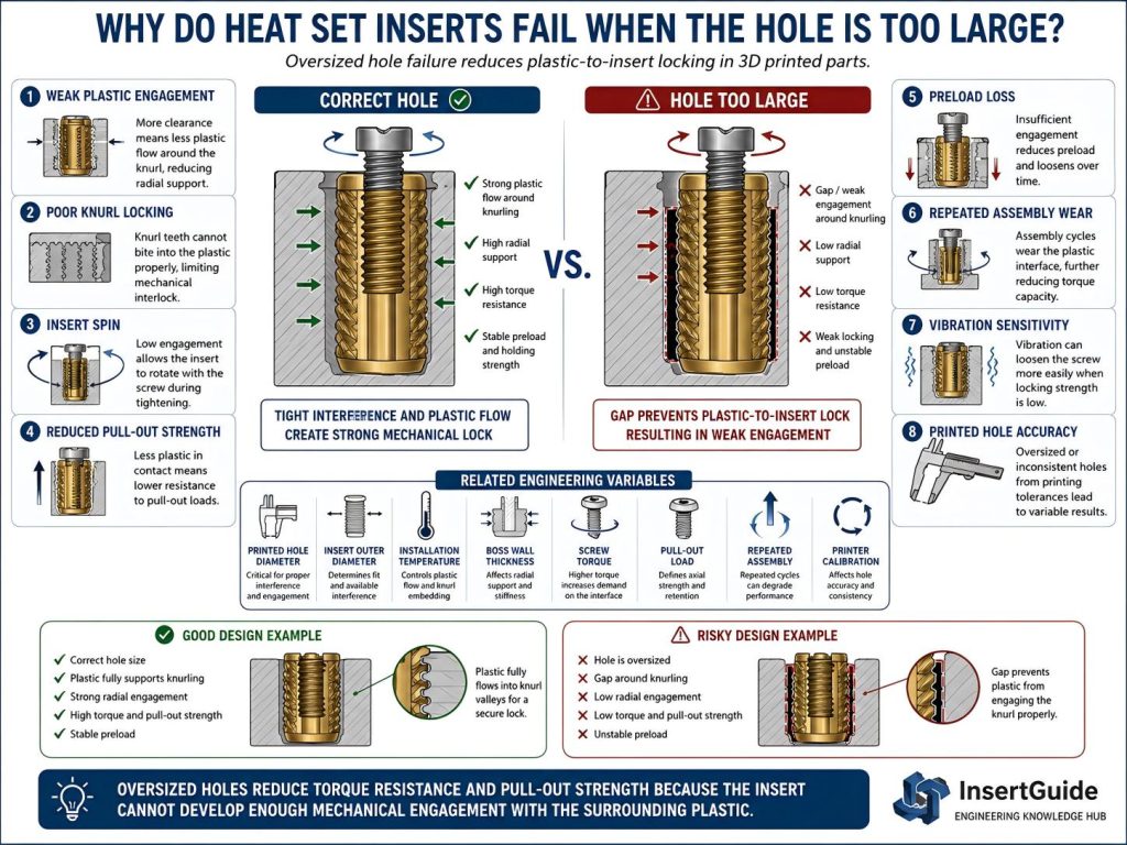
A heat set insert depends on controlled interference between the insert outer diameter and the printed hole. During installation, softened plastic should flow around the knurled or textured outer surface of the insert. If the hole is too large, there is not enough plastic displacement, compression, or radial support around the insert.
The insert may look installed correctly, but the plastic-to-insert interface is weak. Under screw torque, preload, pull-out load, vibration, or repeated assembly, the insert may spin, loosen, pull out, or lose joint stability.
Oversized hole failure is usually an interface locking problem, not an insert strength problem.
Root Causes
Insufficient Plastic Flow Around the Insert
Heat set inserts need softened plastic to flow around their external knurling.
If the hole is too large, the insert enters the printed part without displacing enough material. The knurling may not be fully surrounded by plastic, which reduces mechanical lock.
The insert may sit flush and appear clean, but the interface may not have enough grip to resist screw torque or axial load.
This is why visual installation quality alone does not guarantee fastening strength.
Weak Torque Resistance
An oversized hole reduces the insert’s ability to resist rotation.
When a screw is tightened, torque is transferred from the screw into the insert. The insert then relies on the plastic around its outer surface to resist that torque.
If the hole is too large, the plastic cannot grip the insert strongly enough. The insert may begin to rotate with the screw, especially during tightening, removal, or repeated assembly.
This is one of the most common causes of insert spin in 3D printed parts.
Reduced Pull-Out Strength
Pull-out strength depends on how much plastic is mechanically locked around the insert.
When the hole is oversized, the insert has less surrounding material to resist axial load. If the screw pulls on the insert, the weak interface may allow the insert to move upward or pull out of the part.
A longer insert may help only if the surrounding boss still provides enough material engagement. If the hole is too loose, insert length alone may not fix the problem.
Poor Preload Stability
A screw joint depends on preload.
If the insert is not firmly locked in the printed boss, the joint may not maintain stable clamping force. The screw may feel tight at first, but preload can drop as the insert shifts, rotates slightly, or settles in the oversized hole.
This can lead to loose screws, inconsistent tightening feel, or reduced long-term joint reliability.
Increased Sensitivity to Vibration
Vibration can make an oversized hole problem worse.
A weak insert interface may survive light static load, but vibration can create micro-movement between the insert and the printed plastic. Over time, this movement can enlarge the weak interface and accelerate loosening or insert spin.
This is common in drone parts, robotics assemblies, RC parts, motor mounts, printer assemblies, and serviceable fixtures.
Repeated Assembly Wear
Repeated screw installation and removal can weaken an oversized insert joint quickly.
Each screw cycle applies torque to the insert. If the insert already has weak plastic engagement, repeated assembly can gradually wear or deform the surrounding plastic until the insert feels loose or rotates.
A heat set insert improves thread durability, but it cannot compensate for poor external locking caused by an oversized hole.
Material Shrinkage or Print Inaccuracy
Oversized holes may come from slicer settings, printer calibration, material behavior, or CAD assumptions.
Printed holes often do not match nominal CAD dimensions exactly. Depending on the printer, material, nozzle size, extrusion behavior, and cooling, a hole may print larger or looser than expected.
This is why insert hole size should be based on measured printed holes, not only CAD values.
Related Engineering Variables
Oversized hole failure depends on several connected variables:
- Printed hole diameter
- Insert outer diameter
- Knurl geometry
- Material flow during installation
- Installation temperature
- Boss wall thickness
- Insert depth
- Screw tightening torque
- Pull-out load
- Screw engagement length
- Repeated assembly cycles
- Vibration
- Material shrinkage
- Printer calibration
- Layer adhesion
- Print orientation
These variables should be evaluated together. A slightly oversized hole may work in a low-load part, but fail quickly under repeated assembly, vibration, or high screw torque.
The correct hole size is not just a fit dimension. It is part of the mechanical locking system.
Engineering Interpretation
An oversized hole causes a plastic-to-insert interface failure.
The insert may not crack the boss, and it may not visibly pull out during installation. The failure appears later when the joint is loaded.
Common outcomes include:
- Insert spin from low torque resistance
- Insert loosening from weak radial support
- Pull-out from poor axial retention
- Preload loss from interface movement
- Reduced reuse life after repeated screw cycles
- Vibration-related loosening
This is different from an undersized hole, which usually creates excessive radial stress and may cause boss cracking or deformation during installation.
An oversized hole fails because there is too little engagement.
An undersized hole fails because there is too much forced displacement.
Both are hole size problems, but they create different failure paths.
How to Reduce the Risk
To reduce heat set insert failure from oversized holes:
- Measure printed hole diameter instead of relying only on CAD size.
- Match hole size to the insert outer diameter and material behavior.
- Use the correct pilot hole size for the specific insert.
- Test hole sizes with the actual printer, material, and slicer settings.
- Avoid using screw size as the hole size reference.
- Ensure enough boss wall thickness around the insert.
- Control installation temperature to create proper plastic flow.
- Avoid installing inserts into loose or poorly printed holes.
- Increase local boss support when higher torque or pull-out load is expected.
- Use repeated assembly design rules for serviceable parts.
- Validate fit with sample parts before using inserts in loaded structures.
The goal is controlled interference. The insert should displace enough softened plastic to form a strong mechanical lock without overstressing the boss.
A reliable heat set insert joint starts with the printed hole, not with the screw.
Related InsertGuide Pages
- Heat Set Insert Hole Size Guide
- M3 Heat Set Insert Hole Size for 3D Printed Parts
- Why Do Heat Set Inserts Spin in 3D Printed Parts?
- Why Do Heat Set Inserts Pull Out of 3D Printed Parts?
- Why Do Heat Set Inserts Become Loose Over Time?
- Torque Resistance of Heat Set Inserts in 3D Printed Parts
- Pull-Out Strength of Heat Set Inserts in 3D Printed Parts
- How to Design Bosses for Heat Set Inserts
- What Is the Most Common Reason Heat Set Inserts Fail in 3D Printed Parts?
FAQ
What happens if the heat set insert hole is too large?
If the hole is too large, the insert may not grip the surrounding plastic strongly enough. This can cause insert spin, loosening, pull-out failure, reduced preload stability, or poor repeated assembly performance.
Can an oversized hole still look like a good installation?
Yes. An oversized hole can allow the insert to sit flush and look clean, but the plastic around the insert may not provide enough mechanical locking. The weakness often appears later under screw torque or pull-out load.
Is an oversized hole worse than an undersized hole?
Both can cause failure, but in different ways. An oversized hole usually reduces grip and torque resistance. An undersized hole creates excessive radial stress and may crack or deform the boss.