
M2 heat set insert pull-out strength for 3D printed parts depends on insert length, knurl engagement, pilot hole fit, boss wall thickness, material behavior, layer direction, screw load, and how well the small printed boss transfers load into the surrounding part.
M2 inserts are often used in compact printed parts where space is limited. This makes pull-out strength more sensitive to small geometry changes, print tolerance, boss support, and screw engagement than larger insert sizes.
This guide explains how to think about M2 heat set insert pull-out strength without assuming that the insert alone determines joint reliability.
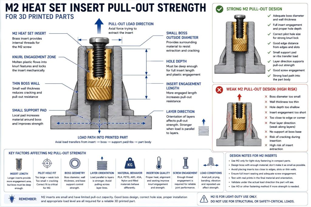
What Pull-Out Strength Means for M2 Heat Set Inserts
Pull-out strength describes the resistance of an insert against being extracted from the printed part along the screw axis. In an M2 heat set insert joint, this may happen when the screw is pulled upward, when a cover is pried open, when a small bracket is loaded, or when repeated screw removal weakens the surrounding plastic.
Because M2 inserts are small, the total engagement area is limited. The printed boss and surrounding material must therefore do their job carefully.
A small insert can work reliably in light-duty parts, but it should not be expected to behave like a larger structural insert.
Why M2 Pull-Out Strength Has a Narrow Design Margin
M2 heat set inserts are used where space is limited: small electronics enclosures, sensor brackets, RC parts, drone covers, compact panels, and lightweight assemblies.
These parts often have:
- Thin boss walls
- Short insert lengths
- Limited hole depth
- Small screw engagement length
- Short edge distance
- Low available tightening torque
- Small load paths into the printed part
As a result, M2 pull-out strength is often controlled by the printed geometry around the insert rather than by the brass insert itself.
Main Variables That Affect M2 Pull-Out Strength
| Variable | Effect on Pull-Out Strength |
|---|---|
| Insert length | Short inserts have limited engagement area and may pull out more easily if the boss is weak. |
| Knurl geometry | External features help the insert lock into the surrounding plastic. |
| Pilot hole size | Controls how much plastic flows into the knurl pattern during installation. |
| Hole depth | Must allow full seating without bottoming or reducing screw engagement. |
| Boss wall thickness | Thin walls reduce plastic support and increase cracking risk. |
| Material | PLA, PETG, ABS, ASA, nylon, and filled materials differ in cracking, creep, and layer adhesion. |
| Print orientation | Layer direction affects whether the boss resists pull-out or separates along layer lines. |
| Screw engagement | Too little usable thread engagement can weaken the joint even if the insert stays in place. |
| Load direction | Axial pull, prying, vibration, and bending loads create different pull-out risks. |
M2 Pull-Out Strength Is Not Only About Insert Size
M2 inserts are small, so they are not intended for high pull-out loads. However, they can be reliable when the joint is designed for light-duty fastening and the boss geometry is appropriate.
The question is not simply whether an M2 insert is strong. The better question is:
Is the printed boss large enough, deep enough, and well supported enough for the load this M2 screw will see?
If the boss is too thin, too close to an edge, or poorly printed, changing the insert brand may not solve the pull-out problem.
How Pilot Hole Size Affects M2 Pull-Out Strength
Pilot hole size controls how the heated insert displaces softened plastic. For M2 inserts, small differences in hole size can have a large effect because the insert and boss are both small.
If the pilot hole is too large, the plastic may not flow tightly enough into the knurl pattern. This can reduce pull-out strength and torque resistance.
If the pilot hole is too small, the boss may crack or deform during insertion, which also reduces pull-out strength.
Oversized-hole risks include:
- Weak knurl engagement
- Insert movement after cooling
- Low pull-out resistance
- Insert spin during screw tightening
- Loose screw feel after repeated assembly
Undersized-hole risks include:
- Boss cracking during installation
- Insert tilt
- Incomplete seating
- Plastic bulging around the insert
- Reduced structural support after cracking
How Boss Geometry Affects M2 Pull-Out Strength
For M2 inserts, boss geometry is often the main limiting factor. A small boss with thin walls may not provide enough plastic volume to resist pull-out load.
Important boss features include:
- Boss outside diameter
- Wall thickness around the insert
- Hole depth
- Boss base support
- Local support pad or rib
- Distance from the insert to the nearest edge
- Connection between the boss and the main part body
A tiny isolated boss may fail even if the insert fits correctly. A slightly larger boss with better support can often improve reliability more than a small change in hole diameter.
Material Behavior and M2 Pull-Out Strength
PLA
PLA can provide stiff small bosses, but it may crack when the pilot hole is too tight or the wall is thin. M2 pull-out performance in PLA depends heavily on avoiding boss cracking during installation.
PETG
PETG is more ductile, which may reduce immediate cracking risk, but small PETG bosses can deform or creep under repeated screw use. Pull-out may not be immediate; the joint may become loose over time.
ABS and ASA
ABS and ASA may handle heat better than PLA and PETG, but small M2 joints still depend on print quality, layer adhesion, and hole precision.
Nylon and Filled Materials
Nylon and fiber-filled materials may offer toughness, but their behavior depends on moisture, fiber content, and print settings. Small M2 bosses in filled materials should be tested because hole quality and fiber texture can affect insert seating and pull-out behavior.
Print Orientation and Layer Direction
Print orientation affects M2 pull-out strength because layer adhesion may be weaker than the plastic itself. If the screw load pulls along a weak layer direction, the boss may separate before the insert fully loses grip.
For M2 inserts, review:
- Whether the insert axis is aligned with the layer direction
- Whether the load pulls across weak layer lines
- Whether the boss base is built from continuous material
- Whether the boss sits on a thin cover or tab
- Whether the screw creates prying or bending load
A small printed boss has less reserve strength, so poor layer direction can matter more than expected.
Screw Engagement and Pull-Out Behavior
M2 screws are small, and usable thread engagement may be limited by insert length, hole depth, and part stack-up. If the screw engagement is too short, the joint may loosen or strip before the insert reaches its expected pull-out capacity.
Check:
- Screw length
- Insert internal thread depth
- Installed insert depth
- Part thickness being clamped
- Washer or bracket thickness
- Whether the screw bottoms out
- Whether enough thread is actually engaged
Pull-out strength should be considered together with screw engagement, not separately.
Load Direction and M2 Pull-Out Risk
M2 inserts are usually best for light-duty fastening. They are less suitable for heavy axial pull, strong prying loads, or high vibration unless the surrounding boss and part structure are carefully reinforced.
Common load conditions include:
- Light cover retention
- Small sensor mounting
- Low-load bracket fastening
- Thin enclosure screw points
- Repeated service access
- Small vibration loads
- Accidental prying during opening
A joint that feels secure during assembly may still loosen if it is used as a structural load point.
Short M2 Inserts and Pull-Out Strength
Many M2 heat set inserts are short because the parts they are used in are compact. Short inserts can work well, but they provide limited engagement area.
Short M2 inserts require:
- Good pilot hole fit
- Clean knurl engagement
- Enough boss wall thickness
- Accurate seating depth
- Controlled insertion heat
- Proper screw length
If more pull-out strength is needed, the answer may be a longer insert, a larger boss, M3 hardware, or a different fastening layout.
How to Improve M2 Heat Set Insert Pull-Out Strength
- Use the exact insert drawing as the starting point.
- Print test bosses in the same material and orientation as the final part.
- Increase local boss diameter when space allows.
- Keep enough wall thickness around the insert.
- Avoid placing M2 inserts too close to edges or corners.
- Add a small support pad or rib when possible.
- Ensure enough hole depth for full insert seating.
- Control insertion heat to avoid over-softening the boss.
- Check screw length and thread engagement.
- Use M3 or another fastening method if the load is too high for M2.
Common M2 Pull-Out Strength Mistakes
- Using M2 inserts for loads that require a larger fastener.
- Making the boss too small because the insert is small.
- Ignoring small-hole print tolerance.
- Using a pilot hole that is too large for reliable knurl engagement.
- Cracking the boss with an undersized hole.
- Overheating the small boss during installation.
- Ignoring screw engagement length.
- Testing only initial fit, not repeated assembly.
- Placing the insert too close to a thin edge.
When M2 Pull-Out Strength May Not Be Enough
M2 heat set inserts may not be enough when the part carries structural load, repeated vibration, high clamping force, frequent disassembly, or strong prying load.
Consider another approach when:
- The part is load-bearing
- The screw will be removed many times
- The joint must resist vibration
- The boss cannot be made thick enough
- The insert is close to an edge
- The screw engagement length is too short
- The part can accept M3 hardware instead
Possible alternatives include M3 inserts, through-bolts, captured nuts, multiple fasteners, local metal reinforcement, or a redesigned joint layout.
Recommended M2 Pull-Out Design Process
- Select M2 only when the load and available space justify a small fastener.
- Check the insert drawing for outer diameter, length, and pilot hole recommendation.
- Design the boss with enough wall thickness and local support.
- Check hole depth, screw length, and usable thread engagement.
- Review edge distance and print orientation.
- Print a test boss in the final material and orientation.
- Install the insert with controlled heat and light vertical pressure.
- Inspect for cracking, tilt, plastic bulging, or poor seating.
- Test screw engagement and expected load direction.
- Use a larger insert or different fastening method if the test boss is marginal.
Related Engineering Guides
- M2 Heat Set Insert Hole Size for 3D Printed Parts
- M2 Heat Set Insert Boss Design for 3D Printed Parts
- M3 Heat Set Insert Pull-Out Strength for 3D Printed Parts
- M4 Heat Set Insert Pull-Out Strength for 3D Printed Parts
- Pull-Out Strength of Heat Set Inserts in 3D Printed Parts
- Layer Adhesion and Heat Set Insert Strength in 3D Printed Parts
- Screw Engagement Length for Heat Set Inserts in 3D Printed Parts
Related Engineering References
- M2 Heat Set Insert Dimensions Reference for 3D Printed Parts
- Boss OD Ratio for Heat Set Inserts in 3D Printed Parts
- Heat Set Insert Minimum Wall Thickness Reference for 3D Printed Parts
- Heat Set Insert Edge Distance Reference for 3D Printed Parts
- Heat Set Insert Hole Depth Chart for 3D Printed Parts
- Heat Set Insert Assembly Stack-Up Reference for 3D Printed Parts
Conclusion
M2 heat set insert pull-out strength is limited by the small scale of the insert and boss. Insert length, knurl engagement, pilot hole fit, wall thickness, material behavior, layer direction, screw engagement, and load path all influence whether the joint can resist extraction.
For compact 3D printed parts, M2 inserts can be reliable when used within their limits. The safest approach is to design the boss, hole, screw engagement, and load path together instead of expecting the small insert to carry more load than the printed structure can support.
Related Decision Resources
For insert selection, tool choice, and supplier comparison, use these decision-focused references after the engineering requirements are defined.