
M2 heat set insert boss design for 3D printed parts requires careful control of boss diameter, wall thickness, hole depth, edge distance, print tolerance, and insertion heat. M2 inserts are small, but the surrounding printed structure still needs enough material to resist cracking, spin-out, pull-out, and screw misalignment.
Because M2 heat set inserts are often used in compact electronics housings, sensor brackets, RC components, small covers, drone parts, and thin printed assemblies, the available boss space is usually limited. This makes M2 boss design less forgiving than it first appears.
A reliable M2 insert joint depends on more than choosing a small pilot hole. The boss must be designed as a miniature fastening structure.
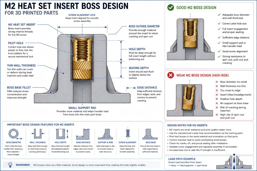
Why M2 Boss Design Matters
M2 heat set inserts are commonly used when space is tight. The part may have thin walls, narrow tabs, shallow covers, or small mounting pads. These conditions reduce the amount of plastic available around the insert.
If the M2 boss is too thin, too close to an edge, or too shallow, the insert may install poorly or fail during use.
Common M2 boss design problems include:
- Boss cracking during insertion
- Insert tilt caused by poor alignment
- Weak screw engagement
- Insert spin-out under light screw torque
- Pull-out failure in small covers or tabs
- Plastic bulging around the insert
- Loss of thread reliability after repeated screw removal
M2 Boss Design Is a Small-Feature Problem
M2 inserts are small enough that normal 3D printing tolerance becomes a major part of the design. A small amount of over-extrusion, hole shrinkage, poor seam placement, or wall thinning can affect the boss more than it would in a larger M4 or M5 structure.
For this reason, M2 bosses should be designed with realistic print behavior in mind. The CAD model may look clean, but the printed boss may have a smaller hole, rougher internal surface, or weaker wall than expected.
The smaller the boss, the less room there is for installation error.
Key Boss Design Variables for M2 Heat Set Inserts
| Design Variable | Why It Matters |
|---|---|
| Boss outside diameter | Controls how much plastic surrounds the M2 insert and resists cracking. |
| Wall thickness | Thin boss walls can split or deform during heat insertion. |
| Pilot hole size | Small hole changes can strongly affect insertion force and knurl engagement. |
| Hole depth | Must allow full insert seating without bottoming or proud installation. |
| Edge distance | M2 bosses near edges or corners have limited support and higher crack risk. |
| Print orientation | Layer direction affects whether the small boss splits or holds load. |
| Material | PLA, PETG, ABS, ASA, nylon, and resin-like materials respond differently to heat and stress. |
| Insertion heat | Small bosses can overheat quickly, weakening the surrounding plastic. |
| Screw alignment | M2 screws are small, so insert tilt can quickly cause assembly problems. |
Boss Outside Diameter for M2 Inserts
The boss outside diameter must provide enough material around the pilot hole to support the insert. Because M2 inserts are small, designers sometimes make the boss too small as well. This can leave very little plastic between the insert and the outside wall.
A boss that is too small may crack during insertion or fail when the screw is tightened. Even if the insert appears seated, the surrounding plastic may not provide enough support for repeated assembly.
When choosing M2 boss size, review:
- Insert outer knurled diameter
- Minimum wall thickness around the hole
- Distance to nearby part edges
- Whether the boss connects to a thin cover or tab
- Whether the screw will be removed repeatedly
- Whether the boss can be reinforced with a pad or rib
Wall Thickness Around an M2 Insert
Wall thickness is critical for M2 boss design because there is not much room around the insert. If the wall is too thin, the heat set insert can push the plastic outward and split the boss.
A thin wall may also reduce the insert’s resistance to spin-out because the surrounding plastic cannot fully support the knurl engagement zone.
For small printed parts, increasing local wall thickness or adding a small reinforced pad can be more useful than simply changing the pilot hole diameter.
Hole Depth and Insert Seating
M2 inserts are often short, but hole depth is still important. The boss must allow the insert to seat fully without bottoming out in a blind hole.
If the hole is too shallow, the insert may sit proud of the surface or leave too little usable screw engagement. If the insert is pressed too far, the screw stack-up may no longer work as intended.
For M2 bosses, check:
- Insert length
- Target seating depth
- Blind hole clearance
- Displaced plastic volume
- Screw length
- Usable thread engagement
- Whether the screw can bottom out
Edge Distance for M2 Bosses
M2 heat set inserts are often placed near the edge of a small enclosure, thin cover, or mounting tab. This can be risky because there may not be enough plastic between the insert and the edge to resist cracking.
Low edge distance can cause:
- Cracks from the pilot hole to the outside edge
- Insert tilt during installation
- Weak pull-out resistance
- Reduced torque resistance
- Local deformation in thin covers
If an M2 insert must be placed near an edge, consider increasing the local pad size, moving the fastener inward, adding a small rib, or using a different fastening layout.
Ribs and Local Pads for M2 Bosses
M2 bosses are often too small for large structural ribs, but small support features can still help. A local pad, widened wall section, or small triangular rib can improve how the boss transfers load into the surrounding part.
Support features are especially useful when the boss is part of a thin enclosure wall or cover. Without support, the boss may behave like a tiny isolated post.
Good support features should be printable and not so thin that they become weak decorative geometry.
Material Behavior in M2 Boss Design
PLA
PLA can print small M2 bosses accurately, but it can crack if the pilot hole is too tight or the wall is thin. M2 inserts in PLA should be installed with controlled heat and light pressure.
PETG
PETG is more ductile than PLA, which may reduce immediate cracking risk, but small PETG bosses can deform if overheated. Repeated screw assembly may also reveal creep or loosening in serviceable parts.
ABS and ASA
ABS and ASA may handle heat better, but small M2 bosses still depend on print quality and hole accuracy. Warping, poor layer adhesion, or rough small holes can reduce reliability.
Nylon and Filled Materials
Nylon and filled materials may behave differently due to moisture, fiber content, and extrusion quality. M2 boss design in these materials should be validated with printed test bosses.
Print Orientation and Small Boss Strength
Print orientation affects how an M2 boss resists cracking, pull-out, and layer separation. A small boss may fail along layer lines if the screw load or insertion pressure opens a weak layer path.
Review whether:
- The insert axis is aligned with or across the layer direction
- The boss base is supported by continuous printed material
- The boss sits on a thin cover or unsupported tab
- The screw load creates bending at the boss base
- The part will be opened repeatedly
For M2 bosses, small geometry errors can combine with weak layer direction and produce early failure.
Designing M2 Bosses for Screw Alignment
Screw alignment is especially important for M2 inserts. A small tilted insert can cause cross-threading, screw binding, uneven clamping, or poor assembly feel.
Insert tilt may be caused by:
- Uneven heat transfer
- Poor pilot hole accuracy
- Too much insertion force
- Thin or flexible boss walls
- No insertion guide or vertical control
- Part movement during installation
For small screws, even a minor alignment error can matter.
Designing M2 Bosses for Torque Resistance
M2 screws use lower torque than M3 or M4 screws, but torque resistance still matters. If the hole is too large, the knurl engagement is weak, or the boss wall is too thin, the insert may spin during tightening.
M2 torque resistance depends on:
- Insert knurl design
- Pilot hole fit
- Plastic flow around the insert
- Boss wall thickness
- Material behavior
- Installation temperature
- Number of screw cycles
Because the insert is small, there is less contact area available. Good boss design helps compensate for the limited scale.
Designing M2 Bosses for Pull-Out Resistance
M2 inserts are not normally chosen for heavy pull-out loads. They are better suited for small covers, light brackets, electronics housings, sensor modules, and low-load assemblies.
Pull-out resistance depends on:
- Insert length
- Knurl engagement
- Hole fit
- Boss depth
- Wall thickness
- Material strength
- Print orientation
- Load direction
If the part needs significant pull-out strength, M3 or a different fastening method may be more appropriate.
Common M2 Boss Design Mistakes
- Making the boss as small as possible without checking wall thickness.
- Placing M2 inserts too close to thin edges.
- Using too much heat and melting the small boss.
- Forcing the insert into an undersized hole.
- Ignoring printed hole shrinkage.
- Using M2 for a load that needs M3 or M4.
- Designing the boss without enough screw engagement depth.
- Ignoring insert tilt in small screw assemblies.
- Testing fit once but not checking repeated screw removal.
When M2 May Be Too Small for the Part
M2 is useful when the part is compact and the screw load is light. It may be too small when the joint requires high torque, frequent service, vibration resistance, or meaningful pull-out load.
Consider M3 or another fastening method if:
- The part carries structural load
- The screw will be removed frequently
- The joint experiences vibration
- The cover needs strong clamping force
- The boss can physically support a larger insert
- The M2 screw engagement is too short
- The boss cracks during test installation
The best insert size is not the smallest one that fits. It is the smallest one that can still meet the fastening requirement reliably.
Recommended M2 Boss Design Process
- Select the M2 insert based on space, screw size, and load requirement.
- Check the insert drawing for outer diameter, length, and pilot hole recommendation.
- Design the boss with enough outside diameter and wall thickness.
- Check edge distance, hole depth, and screw engagement.
- Print a test boss in the same material and orientation as the final part.
- Install the insert with controlled heat and light vertical pressure.
- Check for cracking, tilt, proud seating, and plastic bulging.
- Test screw engagement and light tightening torque.
- Test repeated screw removal if the part is serviceable.
- Adjust boss geometry before relying only on hole diameter changes.
Related Engineering Guides
- M2 Heat Set Insert Hole Size for 3D Printed Parts
- M3 Heat Set Insert Boss Design for 3D Printed Parts
- M4 Heat Set Insert Boss Design for 3D Printed Parts
- How to Design Bosses for Heat Set Inserts
- Heat Set Insert Hole Size Guide
- Screw Engagement Length for Heat Set Inserts in 3D Printed Parts
- PLA vs PETG vs ABS for Threaded Inserts
Related Engineering References
- M2 Heat Set Insert Dimensions Reference for 3D Printed Parts
- Boss OD Ratio for Heat Set Inserts in 3D Printed Parts
- Heat Set Insert Minimum Wall Thickness Reference for 3D Printed Parts
- Heat Set Insert Edge Distance Reference for 3D Printed Parts
- Heat Set Insert Seating Depth Reference for 3D Printed Parts
- Heat Set Insert Assembly Stack-Up Reference for 3D Printed Parts
Conclusion
M2 heat set insert boss design is a small-feature engineering problem. The boss must provide enough wall thickness, hole depth, edge distance, screw alignment, and local support for the insert to work reliably.
For compact 3D printed parts, a reliable M2 insert joint depends on precise hole control, careful heat insertion, and a boss that is strong enough for the intended load without pretending that small size removes structural requirements.
Related Decision Resources
For insert selection, tool choice, and supplier comparison, use these decision-focused references after the engineering requirements are defined.