
M4 heat set insert boss design for 3D printed parts requires more attention to wall thickness, boss outside diameter, hole depth, edge distance, and screw torque than smaller insert sizes. An M4 insert can provide stronger fastening, but only when the surrounding printed structure is large enough to support the insert.
In many 3D printed parts, M4 heat set inserts are used for brackets, fixtures, mounting plates, serviceable covers, motor mounts, and structural prototype assemblies. These applications often involve higher clamp loads and greater tightening torque than M2, M2.5, or M3 inserts.
This means the boss must be designed as part of the fastening system, not as a simple cylinder around a hole.
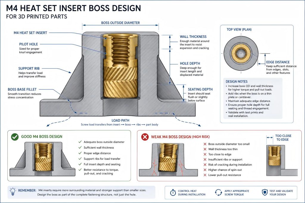
Why M4 Boss Design Matters
An M4 heat set insert is larger than an M3 insert, so it displaces more plastic during installation and applies more radial pressure to the printed boss. It also usually receives a larger screw, which can apply higher torque and clamp load during assembly.
If the boss is too small, too thin, too close to an edge, or poorly supported, the insert may still install successfully but fail later during tightening or service.
Common M4 boss design problems include:
- Boss cracking during insert installation
- Insert spin-out during screw tightening
- Pull-out failure under axial load
- Boss deformation around the insert
- Thread loosening after repeated assembly
- Insert tilt caused by poor installation support
- Surface bulging or local melting around the insert
M4 Boss Design Is Not Just a Larger M3 Boss
It is tempting to scale an M3 boss upward and assume the structure will work for M4. In practice, M4 bosses need more careful review because the larger insert changes the balance between heat, plastic displacement, radial stress, and screw torque.
A good M4 boss should provide enough material around the insert to resist cracking, enough depth for the insert to seat properly, and enough surrounding structure to transfer screw load into the printed part.
If the part does not have room for a strong M4 boss, a smaller insert, through-bolt, metal bracket, or different fastening layout may be more reliable.
Key Boss Design Variables for M4 Heat Set Inserts
| Design Variable | Why It Matters |
|---|---|
| Boss outside diameter | Controls how much plastic surrounds the insert and resists cracking or expansion. |
| Wall thickness | Thin walls around an M4 insert increase the risk of splitting and deformation. |
| Hole size | The pilot hole must allow plastic flow without excessive radial stress. |
| Hole depth | The boss must be deep enough for the insert length, seating depth, and displaced plastic. |
| Edge distance | Low edge distance weakens the boss and increases crack risk near corners or tabs. |
| Print orientation | Layer direction affects splitting, pull-out strength, and boss stiffness. |
| Material | PLA, PETG, ABS, ASA, nylon, and filled materials respond differently to heat and load. |
| Screw torque | M4 screws can apply higher tightening torque, so the boss must support rotational load. |
| Assembly frequency | Repeated screw removal can reveal creep, wear, or progressive loosening. |
Boss Outside Diameter for M4 Inserts
The boss outside diameter must be large enough to provide structural support around the insert. A boss that barely surrounds the M4 insert may crack during installation or fail when screw torque is applied.
The correct boss diameter depends on the insert outer diameter, printed material, wall thickness, load direction, and surrounding geometry. For M4 inserts, the boss usually needs more generous support than a small electronics-style M2 or M3 boss.
The boss should be reviewed together with:
- Insert outer knurled diameter
- Minimum wall thickness around the pilot hole
- Distance to nearby edges, slots, and corners
- Whether the screw load is axial, shear, bending, or vibration-related
- Whether the part will be opened and closed repeatedly
Wall Thickness Around an M4 Insert
Wall thickness is one of the most important M4 boss design variables. If the boss wall is too thin, the plastic may split as the heated insert displaces material outward.
A thin wall may also reduce torque resistance because the surrounding plastic cannot fully support the knurl engagement zone.
For M4 boss design, avoid treating the pilot hole as an isolated feature. The wall around the hole is what converts the insert from a loose brass part into a supported fastening structure.
Hole Depth and Insert Seating
M4 inserts are often longer than smaller inserts, so hole depth becomes more important. A boss must provide enough depth for the full insert length, seating position, and displaced plastic.
If the hole is too shallow, the insert may bottom out before it reaches the intended position. This can leave the insert proud of the surface, reduce screw engagement, or push molten plastic into the wrong area.
If the hole is too deep without enough control, the insert may sink below the intended seating plane or reduce the available thread engagement depending on the part stack-up.
For blind holes, always check:
- Insert length
- Target seating depth
- Bottom clearance
- Displaced plastic volume
- Screw length and engagement
- Whether the screw can bottom out
Edge Distance for M4 Bosses
M4 heat set inserts should not be placed too close to a free edge, corner, slot, or thin tab. Low edge distance reduces the amount of plastic available to resist cracking, spin-out, and pull-out load.
This is especially important when the insert is used in a bracket or mounting plate where screw load may create bending or prying forces.
If an M4 insert must be placed near an edge, consider adding:
- Ribs around the boss
- A larger local pad
- Thicker surrounding walls
- Fillets at boss-to-wall transitions
- More distance from sharp internal corners
- A different fastener layout if space allows
Ribs and Support Features Around M4 Bosses
Because M4 inserts are often used in structural printed parts, ribs can help distribute load from the boss into the surrounding part.
Ribs are especially useful when the boss rises from a flat plate, bracket, cover, or fixture body. They reduce local stress concentration and help prevent the boss from acting like a weak isolated column.
Good rib design should support the boss without creating sharp stress risers. Smooth transitions, fillets, and enough wall thickness are usually more helpful than very thin decorative ribs.
Material Behavior in M4 Boss Design
PLA
PLA can produce stiff bosses, but it is less forgiving when the pilot hole is too tight or the boss wall is too thin. M4 inserts in PLA need conservative boss geometry because cracking during insertion or tightening can occur when radial pressure is high.
PETG
PETG is more ductile than PLA, which can help during insertion, but it may creep under sustained clamp load. M4 bosses in PETG should be checked for long-term preload retention, especially in service covers, brackets, and repeated assembly parts.
ABS and ASA
ABS and ASA may tolerate heat better than PLA and PETG, but print quality, layer adhesion, and boss geometry still control the final fastening performance. M4 bosses in ABS or ASA should still be validated with test prints.
Nylon and Filled Materials
Nylon and fiber-filled materials can behave very differently depending on formulation, moisture, fiber content, and print settings. M4 boss geometry in these materials should be tested because insert retention, heat response, and screw torque behavior may not match unfilled PLA or PETG.
Print Orientation and Layer Direction
Print orientation affects how an M4 boss resists cracking and pull-out load. If the insert load tries to split the part along layer lines, the boss may fail even when the diameter appears large enough.
For M4 inserts used in structural parts, review whether the screw load is pulling along the layer direction, across layer lines, or creating bending stress at the boss base.
Layer adhesion becomes especially important when the boss is tall, narrow, near an edge, or loaded repeatedly.
Designing M4 Bosses for Torque Resistance
M4 screws can apply enough torque to rotate an insert inside the plastic if the boss does not provide sufficient support around the knurl engagement zone.
Torque resistance depends on:
- Insert knurl design
- Pilot hole fit
- Plastic flow around the insert
- Boss wall thickness
- Material stiffness and creep behavior
- Installation temperature
- Final screw tightening torque
If the insert spins during tightening, the problem may not only be the hole size. It may also be weak boss support, overheating, poor knurl engagement, or excessive screw torque.
Designing M4 Bosses for Pull-Out Resistance
Boss geometry should also be checked against M4 pull-out strength requirements.
Pull-out resistance depends on how well the insert is mechanically locked into the printed material and how the boss transfers axial load into the part.
For M4 inserts, pull-out resistance is affected by:
- Insert length
- Knurl engagement depth
- Hole size
- Boss depth
- Material strength
- Layer orientation
- Load direction
- Whether the boss base is reinforced
A larger insert can improve pull-out resistance only if the printed boss has enough surrounding material and layer strength to support the load.
Common M4 Boss Design Mistakes
- Using M4 because it seems stronger without checking available boss space.
- Copying M3 boss proportions without adding enough wall support.
- Placing the insert too close to an edge or slot.
- Making the pilot hole too tight in a thin PLA boss.
- Ignoring screw torque and repeated assembly conditions.
- Using a blind hole that is too shallow for the insert length.
- Forgetting that printed holes may be smaller than the CAD model.
- Installing the insert without checking alignment.
- Designing the boss as an isolated cylinder with no ribs or load path.
When M4 May Be Too Large for the Part
M4 is not always the best choice. If the printed part is small, thin, or close to edges, an M4 insert may require more boss diameter and wall thickness than the part can provide.
In those cases, consider:
- Using M3 instead of M4
- Increasing local boss size
- Adding ribs or a thicker mounting pad
- Moving the fastener away from the edge
- Using a through-bolt and nut
- Changing the joint layout
- Using more smaller fasteners instead of one larger fastener
The strongest fastening choice is not always the largest insert. It is the insert size that the printed structure can support reliably.
Recommended M4 Boss Design Process
- Choose the M4 insert based on screw requirement and available part space.
- Check the manufacturer’s insert outer diameter, length, and pilot hole recommendation.
- Design the boss with enough outside diameter and wall thickness.
- Check edge distance, ribs, and the surrounding load path.
- Confirm hole depth and seating depth.
- Print a test boss in the same material and orientation as the real part.
- Install the insert with controlled heat and vertical pressure.
- Check for cracking, tilt, proud seating, and plastic bulging.
- Test screw tightening torque and repeated assembly if relevant.
- Adjust boss geometry before changing only the hole diameter.
Related Engineering Guides
- M4 Heat Set Insert Hole Size for 3D Printed Parts
- M3 Heat Set Insert Boss Design for 3D Printed Parts
- How to Design Bosses for Heat Set Inserts
- Heat Set Insert Hole Size Guide
- Torque Resistance of Heat Set Inserts in 3D Printed Parts
- Pull-Out Strength of Heat Set Inserts in 3D Printed Parts
- PLA vs PETG vs ABS for Threaded Inserts
Related Engineering References
- M4 Heat Set Insert Dimensions Reference for 3D Printed Parts
- Boss OD Ratio for Heat Set Inserts in 3D Printed Parts
- Heat Set Insert Minimum Wall Thickness Reference for 3D Printed Parts
- Heat Set Insert Edge Distance Reference for 3D Printed Parts
- Heat Set Insert Seating Depth Reference for 3D Printed Parts
- Heat Set Insert Assembly Stack-Up Reference for 3D Printed Parts
Conclusion
M4 heat set insert boss design must support more than the insert hole. The boss needs enough outside diameter, wall thickness, depth, edge distance, and surrounding structure to resist cracking, spin-out, pull-out, and long-term loosening.
For structural 3D printed parts, an M4 insert can be a strong fastening choice only when the printed boss is designed as a load-bearing feature rather than a small cylinder around a brass insert.
Related Decision Resources
For insert selection, tool choice, and supplier comparison, use these decision-focused references after the engineering requirements are defined.