
M4 heat set insert pull-out strength for 3D printed parts depends on insert length, knurl engagement, pilot hole fit, boss geometry, material behavior, layer direction, hole depth, and how the screw load is transferred into the printed structure.
An M4 insert can provide stronger fastening than smaller insert sizes, but only when the surrounding 3D printed boss is designed to support the load. Pull-out strength is not determined by the brass insert alone. It is controlled by the complete interaction between the insert, softened plastic, boss wall thickness, print orientation, and service load.
This guide explains how to evaluate M4 heat set insert pull-out strength in 3D printed parts without treating insert size as the only strength factor.
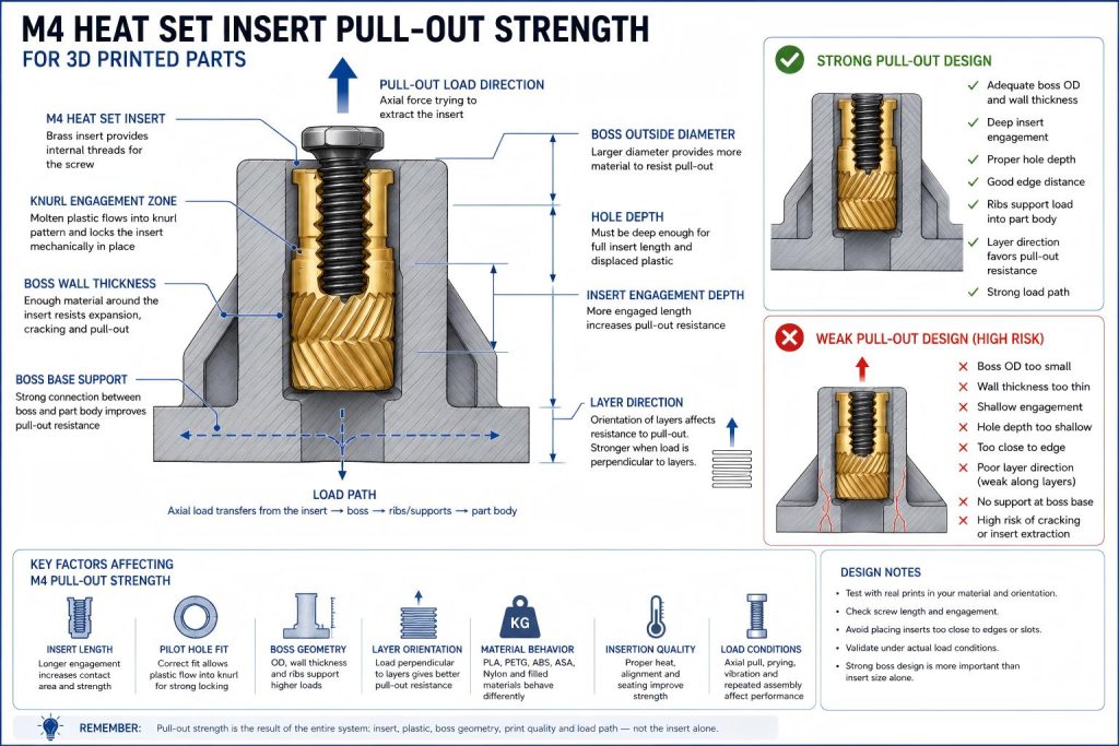
What Pull-Out Strength Means for M4 Heat Set Inserts
Pull-out strength describes the resistance of the insert against being extracted from the printed part along the screw axis. In an M4 heat set insert joint, pull-out failure may occur when axial load, prying force, vibration, or repeated assembly weakens the mechanical grip between the insert and surrounding plastic.
For M4 inserts, pull-out strength is often important in brackets, fixtures, mounting plates, access covers, service panels, machine guards, and structural prototype assemblies.
A stronger screw thread does not automatically mean a stronger printed joint. If the printed boss is weak, thin, poorly supported, or printed in an unfavorable orientation, the insert may still pull out under load.
Why M4 Pull-Out Strength Needs Structural Support
M4 inserts are larger than M3 inserts and are often used with higher clamp loads. This makes the surrounding plastic structure more important, not less important.
A larger insert can provide more contact area and thread engagement, but it also needs:
- Enough boss diameter around the insert
- Sufficient wall thickness to resist cracking and expansion
- A pilot hole that allows proper knurl engagement
- Enough hole depth for full insert seating
- Good layer adhesion in the load direction
- A load path from the boss into the main printed part
- Controlled insertion heat to avoid weak or overheated plastic
If these conditions are not met, an M4 insert may fail by pull-out, boss cracking, insert tilt, or spin-out even though the insert itself is large.
Main Variables That Affect M4 Pull-Out Strength
| Variable | Effect on Pull-Out Strength |
|---|---|
| Insert length | Longer inserts can provide more engagement area, but only if the boss has enough depth and support. |
| Knurl geometry | External features help lock the insert into the surrounding plastic. |
| Pilot hole size | Controls how much plastic is displaced into the insert knurl pattern. |
| Hole depth | Must allow the insert to seat fully without bottoming out. |
| Boss outside diameter | Provides surrounding material to resist expansion, cracking, and extraction. |
| Wall thickness | Thin walls reduce the amount of plastic available to hold the insert. |
| Material | PLA, PETG, ABS, ASA, nylon, and filled materials fail differently under axial load. |
| Print orientation | Layer direction affects whether the boss resists pull-out or separates along layer lines. |
| Insertion quality | Tilted, overheated, underheated, or poorly seated inserts usually reduce joint strength. |
| Load direction | Axial pull, prying, vibration, and bending create different failure risks. |
M4 Pull-Out Strength Is Not Only About Insert Size
A common mistake is assuming that increasing from M3 to M4 automatically increases pull-out strength. This may be true only if the printed part has enough geometry to support the larger insert.
If the M4 boss has thin walls, poor layer orientation, insufficient hole depth, or weak support at the boss base, the larger insert can simply create a larger damaged zone during failure.
The correct question is not only “Is M4 stronger than M3?” The better question is:
Does the printed part have enough material and load path to use the strength of an M4 insert?
How Pilot Hole Size Affects Pull-Out Strength
Pilot hole size controls how the heated insert displaces softened plastic. If the hole is too large, the insert may not create enough mechanical grip. If the hole is too small, the boss may crack or deform during installation.
For pull-out strength, the pilot hole must allow the insert knurl features to become mechanically engaged with the surrounding plastic after cooling.
Possible oversized-hole problems include:
- Weak knurl engagement
- Insert movement after cooling
- Reduced axial retention
- Higher risk of pull-out under screw load
- Spin-out during tightening
Possible undersized-hole problems include:
- Boss cracking during installation
- Excessive radial stress
- Insert tilt
- Plastic bulging around the seating surface
- Incomplete insertion depth
How Boss Geometry Affects M4 Pull-Out Strength
The printed boss is the structure that holds the insert. For M4 heat set inserts, boss geometry is often the limiting factor in pull-out strength.
Important boss features include:
- Boss outside diameter
- Wall thickness around the insert
- Boss height and hole depth
- Boss base support
- Fillets at boss transitions
- Ribs that connect the boss to the surrounding part
- Distance from the insert to nearby edges or corners
A tall, unsupported boss may act like a weak column. A boss close to an edge may split before the insert reaches its expected pull-out capacity. A boss with good wall thickness and ribs can transfer load more effectively into the main part body.
Material Behavior and M4 Pull-Out Strength
PLA
PLA can be stiff and dimensionally accurate, but it can crack when radial pressure or axial load is concentrated around the insert. For M4 pull-out strength, PLA bosses should have conservative wall thickness and good edge distance.
PLA failures may involve cracking around the boss, layer separation, or brittle fracture near the insert.
PETG
PETG is more ductile than PLA, which may help during insertion, but it may also deform over time under sustained load. M4 inserts in PETG can perform well when the boss is properly designed, but long-term preload and creep behavior should be considered.
For serviceable PETG parts, repeated assembly may gradually reduce joint stiffness even when the insert does not immediately pull out.
ABS and ASA
ABS and ASA may tolerate heat better than PLA or PETG, but pull-out strength still depends on print quality, layer adhesion, boss geometry, and insertion control. Warping, poor layer bonding, or weak boss support can reduce performance.
Nylon and Fiber-Filled Materials
Nylon and fiber-filled materials can provide useful toughness, but their behavior depends heavily on formulation, moisture, fiber content, and print settings. M4 pull-out performance in these materials should be validated with test coupons or real part prototypes.
Print Orientation and Layer Direction
Print orientation strongly affects M4 heat set insert pull-out strength. If the pull-out load acts in a direction that separates layers, the joint may fail through layer splitting before the insert itself loses grip.
When designing an M4 insert joint, check:
- Whether the insert axis is parallel or perpendicular to layer lines
- Whether the screw load pulls across weak layer bonds
- Whether the boss base is supported by continuous material
- Whether the part will experience bending or prying forces
- Whether the load path passes through a thin printed wall
A well-sized insert hole cannot compensate for a weak layer orientation in a highly loaded part.
Insertion Quality and Pull-Out Strength
Pull-out strength can be reduced by poor installation. An M4 insert requires enough heat to soften the plastic around the hole, but too much heat can damage the boss and reduce local strength.
Installation issues that reduce pull-out strength include:
- Insert installed at an angle
- Insert not fully seated
- Overheating the boss
- Underheating and forcing the insert
- Plastic pushed into the bottom of a blind hole
- Insert sinking too deep
- Surface bulging around the insert
For M4 inserts, installation control matters because the larger insert transfers more heat and displaces more plastic than smaller sizes.
Load Direction and Pull-Out Risk
Pure axial pull-out is only one possible load condition. In real printed parts, M4 inserts may experience combined loads.
Common load conditions include:
- Axial pull from screw tension
- Prying load from a bracket or cover
- Shear load from a mounted component
- Vibration from motors or moving assemblies
- Repeated opening and closing of service panels
- Bending load at the boss base
A joint that survives simple tightening may still fail when the printed part is loaded in bending or vibration.
Short vs Long M4 Inserts
Longer M4 inserts can increase contact area and may improve pull-out resistance, but only if the boss has enough depth and the printed material can support the longer engagement zone.
A longer insert can create problems if:
- The blind hole is too shallow
- The boss is too thin or unsupported
- The insert bottoms out before seating
- The screw engagement conflicts with the hole depth
- The installation overheats too much surrounding plastic
Longer inserts are not automatically better. They must match the boss geometry and expected load.
How to Improve M4 Heat Set Insert Pull-Out Strength
- Use the manufacturer’s pilot hole recommendation as the starting point.
- Print test bosses in the same material and orientation as the final part.
- Increase boss outside diameter when space allows.
- Use adequate wall thickness around the insert.
- Avoid placing M4 inserts too close to edges or corners.
- Add ribs or local pads to support the boss base.
- Ensure enough hole depth for full insert seating.
- Control insertion heat and vertical alignment.
- Check screw length and engagement.
- Test the joint under the actual load direction, not only by hand tightening.
Common M4 Pull-Out Strength Mistakes
For the adjacent rotational retention behavior, see M4 torque resistance.
- Assuming M4 is automatically strong because it is larger than M3.
- Using a weak boss with a large insert.
- Ignoring print orientation and layer adhesion.
- Choosing a pilot hole only from a generic chart without test fitting.
- Using insufficient hole depth for a long insert.
- Placing the insert too close to an edge.
- Testing screw fit but not axial load or repeated assembly.
- Using high screw torque in a boss that cannot support it.
- Ignoring creep in PETG or other ductile materials.
When M4 Pull-Out Strength May Not Be Enough
Some parts should not rely only on M4 heat set inserts for axial retention. If the joint carries high load, impact, safety-critical forces, or repeated vibration, a different fastening strategy may be needed.
Alternatives may include:
- Through-bolts and nuts
- Metal backing plates
- Multiple smaller fasteners
- Larger local mounting pads
- Captured nuts
- Redesigned load paths
- Hybrid printed and metal structures
A heat set insert is strongest when it is used within the limits of the printed structure around it.
Recommended M4 Pull-Out Design Process
- Select the M4 insert based on screw requirement and available part geometry.
- Check the insert drawing for outer diameter, length, and pilot hole recommendation.
- Design the boss with enough outside diameter, wall thickness, and depth.
- Check edge distance and boss base support.
- Review print orientation relative to the pull-out load.
- Print a test boss or prototype using the same material and settings.
- Install the insert with controlled heat and alignment.
- Inspect for cracking, tilt, proud seating, or overheating.
- Test screw tightening and axial load under realistic conditions.
- Adjust boss geometry before assuming the insert size is the problem.
Related Engineering Guides
- M4 Heat Set Insert Hole Size for 3D Printed Parts
- M4 Heat Set Insert Boss Design for 3D Printed Parts
- M3 Heat Set Insert Pull-Out Strength for 3D Printed Parts
- Pull-Out Strength of Heat Set Inserts in 3D Printed Parts
- Torque Resistance of Heat Set Inserts in 3D Printed Parts
- Layer Adhesion and Heat Set Insert Strength in 3D Printed Parts
- PLA vs PETG vs ABS for Threaded Inserts
Related Engineering References
- M4 Heat Set Insert Dimensions Reference for 3D Printed Parts
- Boss OD Ratio for Heat Set Inserts in 3D Printed Parts
- Heat Set Insert Minimum Wall Thickness Reference for 3D Printed Parts
- Heat Set Insert Edge Distance Reference for 3D Printed Parts
- Heat Set Insert Hole Depth Chart for 3D Printed Parts
- Heat Set Insert Assembly Stack-Up Reference for 3D Printed Parts
Conclusion
M4 heat set insert pull-out strength is controlled by more than insert size. The insert length, knurl engagement, pilot hole fit, boss wall thickness, print orientation, material behavior, installation quality, and load path all affect whether the joint can resist axial extraction.
For structural 3D printed parts, an M4 insert should be treated as part of a complete fastening system. The printed boss must be strong enough to use the insert’s potential strength without cracking, loosening, or pulling out under service load.
Related Decision Resources
For insert selection, tool choice, and supplier comparison, use these decision-focused references after the engineering requirements are defined.