
Heat set inserts for battery pack service covers are used when a 3D printed battery enclosure needs a removable cover, access plate, inspection lid, charging-port cover, wiring service panel, or maintenance door that may be opened and closed more than once.
This application is different from a sealed one-time battery housing. A battery pack service cover may need to survive repeated screw removal, preload changes, local boss stress, temperature variation, vibration, and long-term material behavior around the insert joint.
For the broader battery enclosure context, see Heat Set Inserts in Battery Enclosures.
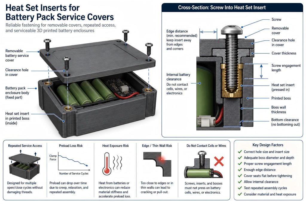
Why Battery Pack Service Covers Need a Specific Insert Design Approach
Battery pack service covers are often used in 3D printed electronics, robotics, portable devices, RC systems, test equipment, and prototype power modules. Unlike a permanent enclosure, the cover may need to be removed for battery replacement, wiring inspection, charging access, connector repair, balance lead access, or thermal inspection.
This repeated access changes the fastening problem. The insert joint may need to handle:
- repeated screw removal and reinstallation
- screw preload loss after service cycles
- plastic creep under sustained clamp force
- boss cracking near thin battery compartment walls
- edge or corner stress around compact covers
- vibration from mobile or robotic assemblies
- heat exposure from battery operation or enclosed electronics
- misalignment when the cover is removed and reinstalled
For this reason, battery pack service covers should be designed as repeated-service fastening structures, not just as simple lids with screws.
Typical Battery Pack Service Cover Use Cases
Heat set inserts may be useful in battery pack designs when the cover needs to be removable without damaging printed plastic threads.
Common examples include:
- removable battery doors
- battery inspection covers
- charging-port service panels
- BMS access covers
- wiring and connector service panels
- RC battery compartments
- robot battery covers
- portable electronics battery housings
- prototype power module covers
- test fixture battery access panels
In these applications, the insert helps provide a reusable metal thread so the cover can be removed and reinstalled during service, testing, or maintenance.
Main Failure Modes in Battery Pack Service Covers
Insert Loosening After Repeated Service
A battery cover may feel secure after the first assembly but become loose after repeated removal. This can happen when the hole is oversized, the insert knurls do not grip enough plastic, the boss is weak, or the printed material relaxes under long-term clamp load.
See also: Why Do Heat Set Inserts Become Loose Over Time?
Preload Drop Around the Cover
A service cover depends on screw preload to stay seated. If preload drops, the cover may rattle, shift, leak dust, lose alignment, or transfer load unevenly into the surrounding battery enclosure.
See also: Why Does Screw Preload Drop in 3D Printed Insert Joints?
Boss Cracking Near Thin Walls
Battery compartments often have compact geometry. If the insert is placed near a thin wall, edge, connector opening, or corner, the boss may crack during installation or repeated screw tightening.
See also: Why Do Heat Set Inserts Fail in Thin Wall 3D Printed Parts?
Edge or Corner Failure
Battery covers are often placed near enclosure edges. If the insert is too close to the edge, the local load path becomes weak and the wall may split, deform, or lose support during repeated service.
See also: Why Do Heat Set Inserts Fail Near Edges or Corners?
Battery Enclosure-Specific Failure
Battery enclosures may combine heat, vibration, repeated access, and compact internal space. If the insert joint is not designed with these conditions in mind, the cover may loosen even if the insert initially installs correctly.
See also: Why Do Heat Set Inserts Fail in Battery Enclosures?
Design Variables for Battery Pack Service Covers
A reliable battery pack service cover should be designed around the full fastening structure, not only around the insert size.
| Design Variable | Why It Matters in Battery Pack Service Covers |
|---|---|
| Insert size | Affects thread engagement, torque resistance, and available boss geometry. |
| Hole size | Controls plastic flow, insert grip, installation stress, and long-term retention. |
| Boss diameter | Determines how much printed material supports the insert during repeated tightening. |
| Boss depth | Helps prevent proud inserts, bottoming, and weak axial support. |
| Screw engagement length | Controls clamp stability without bottoming out inside the insert or below the boss. |
| Cover thickness | Affects screw length selection, seating behavior, and clamp force distribution. |
| Edge distance | Reduces the risk of cracking near enclosure walls, corners, and access openings. |
| Material behavior | PLA, PETG, ABS, and nylon respond differently to preload, heat, creep, and repeated assembly. |
| Battery heat exposure | Heat can reduce plastic stiffness and accelerate preload loss in the insert joint. |
For general hole design, see the Heat Set Insert Hole Size Guide. For boss geometry, see How to Design Bosses for Heat Set Inserts.
Recommended Fastening Structure
For battery pack service covers, the heat set insert is usually best installed in the enclosure base, battery compartment wall, or fixed printed housing. The removable service cover should use clearance holes for the screws.
This allows the screw to clamp the cover into the fixed enclosure without cutting or wearing plastic threads in the cover itself.
A typical battery pack service cover structure includes:
- heat set inserts installed in the fixed enclosure body
- clearance holes in the removable cover
- enough boss diameter around each insert
- enough boss depth for full insert seating
- controlled screw engagement length
- adequate edge distance around cover corners
- a cover that seats flat before screw tightening
The screw should clamp the cover. It should not be used to force a warped battery cover into position.
Cover Seating and Clamp Force
A battery pack service cover should sit flat before final tightening. If the cover is warped, misaligned, or pressing against internal battery cells, wires, connectors, foam pads, or a BMS board, screw tightening may introduce unwanted bending load into the inserts.
Uneven cover seating can cause:
- uneven preload between screws
- localized boss stress
- corner lifting
- cover rattling
- insert loosening after service
- cracking near thin walls or screw bosses
The cover should be designed so the fastening system holds the cover closed, not so the screws compensate for poor internal clearance.
Screw Engagement and Screw Length
Screw engagement length should be long enough to support repeated tightening, but not so long that the screw bottoms out inside the insert or below the boss.
Battery pack service covers may be opened for inspection, charging access, or replacement. A screw that is too short may not provide stable clamp force. A screw that is too long may create false tightening resistance or push against the bottom of the insert cavity.
When checking screw engagement, consider:
- cover thickness
- washer thickness, if used
- insert thread depth
- boss depth
- clearance below the insert
- expected number of service cycles
- whether the cover needs to resist vibration or movement
For deeper reference, see Screw Engagement Length for Heat Set Inserts in 3D Printed Parts.
Material Behavior in Battery Pack Covers
Material choice affects how the insert joint behaves under repeated service, clamp force, and heat exposure.
PLA can provide stiffness, but it may crack if the boss is thin, the hole is too tight, or the enclosure is exposed to elevated temperature. PETG is tougher, but it may creep under sustained screw preload. ABS can tolerate installation heat better than PLA, but still depends on boss design, hole fit, and enclosure geometry. Nylon and carbon fiber nylon may provide better toughness, but printed tolerance, moisture behavior, and local stress concentration still matter.
Battery enclosures can also experience local heat from cells, charging components, electronics, or enclosed air. Heat can reduce plastic stiffness and accelerate preload loss, especially in materials that soften at lower temperatures.
For material comparison, see PLA vs PETG vs ABS for Threaded Inserts.
Repeated Assembly and Service Access
A battery pack service cover may be opened more often than expected during prototyping, repair, charging system changes, wiring inspection, or cell replacement. Each service cycle can slightly change the joint condition.
Repeated service can contribute to:
- insert movement inside the boss
- screw thread wear
- plastic compression under the screw head
- preload relaxation
- cover seating changes
- boss cracking after multiple cycles
For broader repeated assembly behavior, see Heat Set Inserts for Repeated Assembly in 3D Printed Parts.
Thermal and Safety Design Boundaries
Heat set inserts can improve fastening reliability, but they do not solve battery safety problems. A printed battery enclosure should still be designed with appropriate electrical clearance, thermal management, cell spacing, wire routing, strain relief, and material suitability.
The insert should not press directly into a battery cell, wire harness, connector, BMS board, or any component that could be damaged by screw force. The fastening structure should hold the cover, not compress sensitive battery components.
For service covers, check:
- whether screw tips can contact internal components
- whether the boss intrudes into the battery space
- whether the cover compresses wires or cells
- whether heat exposure may soften the printed material
- whether repeated opening changes wire routing or strain relief
This article focuses on fastening structure, not electrical battery safety certification. Battery pack design may require additional safety standards depending on the application.
Repeated Service Design Checks
Before relying on heat set inserts in a battery pack service cover, check the following:
- Confirm the insert dimensions and recommended printed hole size.
- Print a test coupon using the same material and print settings.
- Check that the cover seats flat before screw tightening.
- Confirm that screw tips cannot contact battery cells, wires, connectors, or electronics.
- Make sure the insert boss does not interfere with the battery compartment.
- Check edge distance around cover corners and thin walls.
- Verify screw engagement without bottoming out.
- Test several removal and reassembly cycles.
- Inspect the boss for cracks after installation and repeated service.
- Check whether heat exposure changes cover fit or screw preload.
When Heat Set Inserts Are a Good Fit
Heat set inserts are a good fit for battery pack service covers when the design needs:
- repeated access to the battery compartment
- stronger threads than printed plastic threads
- controlled screw engagement
- serviceable covers for wiring or BMS inspection
- better long-term fastening than self-tapping screws in plastic
- compact but reusable fastening points
They are especially useful in prototypes, robotics battery modules, RC battery compartments, portable electronics, and test equipment that may need repeated opening.
When the Design Needs More Caution
Heat set inserts need more caution when:
- the enclosure wall is very thin
- the insert is close to a battery cell or wire path
- the boss is near a corner or edge
- the cover is warped or under bending load
- the part is printed in PETG under sustained preload
- the battery pack may get warm during use or charging
- the screw may be removed frequently
- the insert boss intrudes into limited internal battery space
If the broader enclosure structure is the main design question, see Heat Set Inserts in Battery Enclosures.
Practical Summary
Heat set inserts for battery pack service covers should be designed as repeated-service fastening points. The insert, screw, boss, cover, printed material, edge distance, screw engagement length, and thermal environment all affect reliability.
A good service cover should be removable without damaging the insert joint, cracking the boss, compressing internal battery components, or losing preload too quickly after repeated access.
For battery pack covers, the key question is not only whether the screw holds the cover once. The more important question is whether the cover remains reliable after service access, heat exposure, repeated tightening, and long-term material behavior.
FAQ
Are heat set inserts useful for battery pack service covers?
Yes. Heat set inserts are useful when a battery pack cover needs to be removed and reinstalled during inspection, battery replacement, wiring service, or prototype development.
Should the insert be installed in the cover or the enclosure body?
In most designs, the insert should be installed in the fixed enclosure body or battery compartment structure. The removable cover should usually use clearance holes.
Why do inserts loosen in battery service covers?
Inserts can loosen because of repeated screw removal, oversized holes, weak boss geometry, preload loss, material creep, heat exposure, or excessive tightening torque.
Can PETG be used for battery pack service covers?
PETG can be used, but it may creep under sustained clamp force and may lose preload over time. If the battery compartment gets warm, the fastening structure should be tested under realistic conditions.
What is the main risk when using inserts near battery cells?
The screw, insert boss, or cover should not press directly into battery cells, wires, connectors, or electronics. Internal clearance and screw length must be checked carefully.
Should battery service covers be tested through repeated assembly cycles?
Yes. Repeated removal and reassembly can reveal insert loosening, boss cracking, screw bottoming, preload loss, cover seating problems, and heat-related material behavior.
Related Guides
- Heat Set Inserts in Battery Enclosures
- Why Do Heat Set Inserts Fail in Battery Enclosures?
- Heat Set Inserts for Repeated Assembly in 3D Printed Parts
- Why Do Heat Set Inserts Become Loose Over Time?
- Why Does Screw Preload Drop in 3D Printed Insert Joints?
- Why Do Heat Set Inserts Fail Near Edges or Corners?
- Why Do Heat Set Inserts Fail in Thin Wall 3D Printed Parts?
- PLA vs PETG vs ABS for Threaded Inserts