
Heat set inserts for adjustable camera and sensor mounts are used when a 3D printed bracket must hold a camera, sensor, lens module, proximity sensor, inspection camera, or alignment device while still allowing adjustment, repositioning, or service access.
This application is different from a fixed sensor bracket. In an adjustable mount, the insert joint may experience repeated loosening and tightening, angle correction, clamp force changes, vibration, slot-hole loading, and torque applied during repositioning. The design goal is not only to hold the sensor once, but to keep the mounting structure stable after repeated adjustment.
For the broader sensor bracket context, see Heat Set Inserts in Sensor Brackets.
Why Adjustable Mounts Need a Specific Insert Design Approach
Camera and sensor mounts are often adjusted during calibration, testing, inspection, robotics tuning, optical alignment, or machine setup. A fixed bracket may only need to hold position after assembly. An adjustable mount must hold position after being moved, tightened, loosened, and tightened again.
This creates a different fastening problem. The insert joint may need to resist:
- repeated screw tightening
- angle adjustment loads
- slot-hole sliding force
- vibration near motors or moving equipment
- preload loss after repositioning
- local boss deformation
- insert spin during clamp tightening
- creep in PETG or other ductile materials
For this reason, adjustable camera and sensor mounts should be designed as clamp-and-reposition fastening structures, not just as static printed brackets.
Typical Adjustable Camera and Sensor Mount Use Cases
Heat set inserts may be useful in 3D printed adjustable mounts when the mounted device needs repeatable positioning or occasional service adjustment.
Common examples include:
- machine vision camera mounts
- robot camera brackets
- inspection camera mounts
- adjustable sensor brackets
- proximity sensor mounts
- limit switch sensor supports
- LiDAR or distance sensor mounts
- optical alignment brackets
- 3D printer camera mounts
- test fixture sensor holders
In these applications, the insert helps provide a more durable thread than printed plastic, especially when the screw may be adjusted more than once.
Main Failure Modes in Adjustable Mounts
Insert Spin During Tightening
Adjustable mounts often require the screw to be tightened enough to hold angle or position. If the insert does not have enough torque resistance, the insert may rotate inside the printed boss instead of clamping the mount.
See also: Why Do Heat Set Inserts Spin in 3D Printed Parts?
Preload Loss After Repositioning
When a camera or sensor mount is loosened and retightened, the screw preload may not return to the same level. Plastic compression, washer seating, slot-hole wear, and material creep can reduce clamping force over time.
See also: Why Does Screw Preload Drop in 3D Printed Insert Joints?
Vibration-Related Movement
Camera and sensor mounts may be attached to machines, robots, printers, motors, or mobile equipment. Vibration can reduce clamp stability and allow the mounted device to drift out of alignment.
See also: Why Do Heat Set Inserts Fail Under Vibration?
Boss Cracking Around the Insert
If the boss wall is too thin or the insert hole is too tight, the boss may crack during installation or during repeated screw tightening. This is especially important in compact sensor mounts where the insert may be close to an edge or thin wall.
See also: Why Do Bosses Crack Around Heat Set Inserts?
Sensor Alignment Drift
An adjustable mount can fail even if the insert does not visibly pull out or spin. If the clamp force drops, the bracket flexes, or the screw seating changes, the camera or sensor may slowly lose its intended alignment.
See also: Why Do Heat Set Inserts Fail in Sensor Brackets?
Design Variables for Adjustable Camera and Sensor Mounts
A reliable adjustable mount should be designed around the complete clamp structure, not only around the insert size.
| Design Variable | Why It Matters in Adjustable Mounts |
|---|---|
| Insert size | Affects thread engagement, torque resistance, and available boss geometry. |
| Hole size | Controls plastic flow, insert grip, installation stress, and long-term insert retention. |
| Boss diameter | Determines how much material supports the insert during repeated clamp tightening. |
| Screw engagement length | Controls thread contact and clamp stability without bottoming out. |
| Slot-hole geometry | Affects how the mount moves during adjustment and how clamp load is distributed. |
| Washer contact area | Helps distribute clamp force and reduce local plastic indentation. |
| Mount stiffness | A flexible bracket may lose alignment even if the insert remains secure. |
| Vibration exposure | Can reduce preload and cause camera or sensor position drift. |
| Material behavior | PLA, PETG, ABS, nylon, and carbon fiber nylon respond differently to preload, heat, and repeated adjustment. |
For general hole design, see the Heat Set Insert Hole Size Guide. For boss geometry, see How to Design Bosses for Heat Set Inserts.
Recommended Fastening Structure
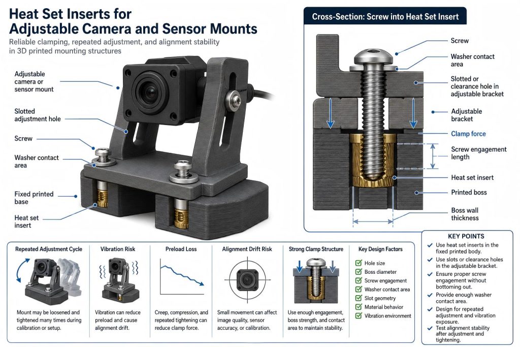
For adjustable camera and sensor mounts, the heat set insert is usually best placed in the fixed base, bracket body, or mounting block. The adjustable component should use a clearance hole, slot, or curved adjustment slot depending on the required movement.
A typical adjustable mounting structure includes:
- a heat set insert installed in the fixed printed body
- a clearance hole or slot in the adjustable bracket
- a screw that clamps the adjustable part against the fixed body
- enough washer or screw-head contact area to distribute pressure
- enough boss diameter around the insert
- controlled screw engagement length
- enough bracket stiffness to hold alignment
The screw should clamp the adjustable part in position. It should not be used to force a warped or flexible bracket into alignment.
Slot Holes and Clamp Force
Many adjustable camera and sensor mounts use straight slots, curved slots, or elongated holes. These features allow position adjustment, but they also change how clamp force enters the printed part.
A slot can reduce local material support around the screw head. If the slot is too narrow, rough, weak, or unsupported, the screw may dig into the plastic instead of holding the mount with stable clamp force.
For adjustable mounts, consider:
- using enough contact area under the screw head
- using washers when the plastic surface is soft or thin
- keeping slot edges smooth and supported
- avoiding very thin material around the slot
- checking whether the bracket flexes during tightening
- testing whether the mount holds alignment after vibration
Clamp force matters more than the visual appearance of the adjustment slot. A clean slot shape is not enough if the screw cannot maintain stable pressure.
Screw Engagement and Adjustment Stability
Screw engagement length should be long enough to support repeated clamp tightening, but not so long that the screw bottoms out inside the insert or below the boss.
Adjustable mounts may be loosened and retightened many times during calibration. A screw that is too short may not provide stable clamp force. A screw that is too long may create false tightening resistance or damage the insert joint.
When checking screw engagement, consider:
- adjustable bracket thickness
- slot depth or washer thickness
- insert thread depth
- boss depth
- clearance below the insert
- expected number of adjustment cycles
- vibration level near the camera or sensor
For deeper reference, see Screw Engagement Length for Heat Set Inserts in 3D Printed Parts.
Torque Resistance in Adjustable Mounts
Adjustable mounts often require enough tightening torque to hold position. If the insert has poor torque resistance, the screw may rotate the insert instead of clamping the bracket.
Torque resistance depends on hole size, insert geometry, knurl engagement, boss diameter, material behavior, and installation quality. In adjustable mounts, torque resistance is especially important because the screw may be tightened repeatedly.
For a deeper explanation, see Torque Resistance of Heat Set Inserts in 3D Printed Parts.
Material Behavior in Camera and Sensor Mounts
Material choice affects how well the mount holds alignment after adjustment.
PLA can provide stiffness, which may help with camera or sensor stability, but it can crack around tight inserts or thin bosses. PETG is tougher, but it may creep under sustained clamp force. ABS can tolerate heat better than PLA, but still depends on boss design and hole fit. Nylon and carbon fiber nylon may be useful in more demanding mounts, but printed tolerance and moisture behavior should be considered.
If the mount is near a motor, heated electronics, enclosed machine space, or outdoor environment, thermal behavior should also be considered. Heat can reduce plastic stiffness and increase preload loss.
For material comparison, see PLA vs PETG vs ABS for Threaded Inserts.
Vibration and Alignment Drift
A camera or sensor mount may fail by losing alignment rather than by breaking visibly. Small shifts can affect image quality, sensor triggering distance, inspection accuracy, or robot calibration.
Vibration can cause:
- preload loss
- micro-movement at the slot
- washer seating changes
- plastic indentation under the screw head
- insert movement inside the boss
- sensor angle drift
To reduce vibration-related movement, the mount should have enough stiffness, stable screw engagement, adequate boss support, and enough clamp contact area. For vibration failure logic, see Why Do Heat Set Inserts Fail Under Vibration?.
Repeated Adjustment Design Checks
Before relying on heat set inserts in an adjustable camera or sensor mount, check the following:
- Confirm the insert dimensions and recommended hole size.
- Print a test coupon using the same material and print settings.
- Check whether the insert resists screw tightening torque.
- Confirm the screw does not bottom out.
- Check whether the adjustable bracket seats flat before tightening.
- Use enough contact area under the screw head or washer.
- Check whether slot edges deform after repeated adjustment.
- Test whether the mount holds alignment after vibration.
- Inspect the boss for cracks after installation and repeated tightening.
- Check whether PETG or softer materials lose clamp force over time.
For repeated fastening behavior, see Heat Set Inserts for Repeated Assembly in 3D Printed Parts.
When Heat Set Inserts Are a Good Fit
Heat set inserts are a good fit for adjustable camera and sensor mounts when the design needs:
- repeated angle adjustment
- better thread durability than printed plastic threads
- controlled clamp force
- stable sensor alignment
- serviceable camera brackets
- reusable machine vision mounts
- stronger fastening in compact printed brackets
They are especially useful when the mount will be adjusted during setup, calibration, prototyping, or maintenance.
When the Design Needs More Caution
Heat set inserts need more caution when:
- the mount is very thin
- the insert is close to an edge or slot
- the bracket is flexible
- the camera or sensor is heavy
- the mount is exposed to vibration
- the screw is adjusted frequently
- the material is PETG under sustained clamp force
- the slot hole is used as part of the load path
If the bracket is mostly a fixed support rather than an adjustable mount, see Heat Set Inserts in Sensor Brackets.
Practical Summary
Heat set inserts for adjustable camera and sensor mounts should be designed as clamp-and-reposition fastening structures. The insert, screw, boss, slot geometry, washer contact area, mount stiffness, material behavior, and vibration environment all affect reliability.
A good adjustable mount should allow the camera or sensor to be repositioned without causing insert spin, boss cracking, preload loss, slot deformation, or alignment drift.
For adjustable mounts, the key question is not only whether the screw holds the bracket once. The more important question is whether the mount can hold alignment after adjustment, tightening, vibration, and repeated use.
FAQ
Are heat set inserts useful for adjustable camera and sensor mounts?
Yes. Heat set inserts are useful when a 3D printed camera or sensor mount needs repeated adjustment, stronger threads, and more reliable clamp force than printed plastic threads can provide.
Should the insert be placed in the fixed body or the adjustable bracket?
In most designs, the insert should be placed in the fixed body or mounting block. The adjustable bracket usually uses a clearance hole, slot, or curved slot so the screw can clamp it into position.
Why do adjustable mounts lose alignment?
Adjustable mounts may lose alignment because of preload loss, vibration, slot deformation, plastic creep, weak boss support, poor screw engagement, or insufficient clamp contact area.
Can PETG be used for adjustable sensor mounts?
PETG can be used, but it may creep under sustained clamp force. If the mount must hold precise alignment, repeated adjustment and preload stability should be tested.
Do slot holes make insert joints weaker?
Slot holes can reduce local support if they are too close to the insert, too thin, or poorly supported. The slot should provide adjustment without weakening the clamp path or boss structure.
Should adjustable mounts be tested after repeated tightening?
Yes. Repeated loosening and tightening can reveal insert spin, boss cracking, slot wear, preload loss, and alignment drift before the mount is used in a final machine or robot.
Related Guides
- Heat Set Inserts in Sensor Brackets
- Why Do Heat Set Inserts Fail in Sensor Brackets?
- Heat Set Insert Hole Size Guide
- How to Design Bosses for Heat Set Inserts
- Screw Engagement Length for Heat Set Inserts in 3D Printed Parts
- Torque Resistance of Heat Set Inserts in 3D Printed Parts
- Why Do Heat Set Inserts Fail Under Vibration?
- Why Does Screw Preload Drop in 3D Printed Insert Joints?