
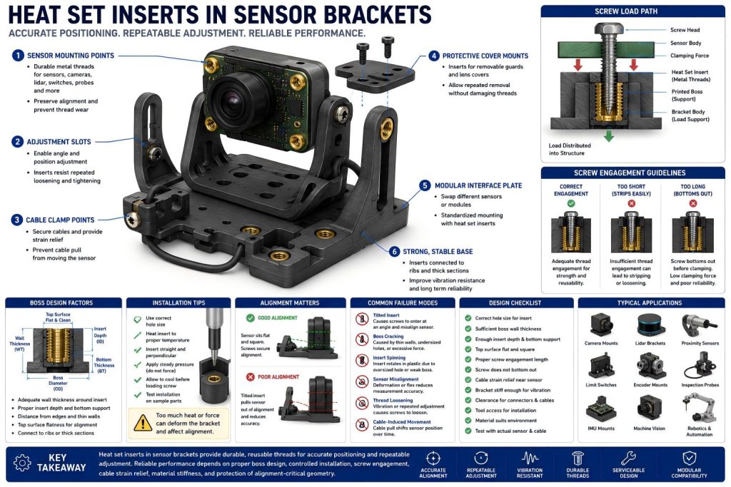
Heat set inserts in sensor brackets are used to create durable threaded points for sensors, cameras, switches, probes, encoder modules, lidar units, and inspection devices that need accurate positioning and repeatable adjustment. In 3D printed sensor brackets, the insert does not only hold a screw. It helps preserve alignment, serviceability, and vibration resistance over repeated use.
Sensor brackets are different from heavy load brackets. They may not carry large forces, but they often control measurement accuracy, orientation, distance, and repeatable positioning.
A weak or distorted insert boss can shift a sensor angle. A tilted insert can pull a sensor body out of alignment. A loose screw can introduce vibration noise. An overheated mounting point can deform the reference surface.
The key point is:
Heat set inserts in sensor brackets should support accurate positioning, not just provide stronger threads.
Why Sensor Brackets Use Heat Set Inserts
Sensor brackets are common in robotics, automation equipment, drones, CNC fixtures, inspection tools, electronics enclosures, test stands, and small machines. These brackets often need to hold small devices in a fixed position while still allowing removal, replacement, or adjustment.
Common sensor bracket applications include:
- camera mounts
- lidar brackets
- proximity sensor holders
- limit switch mounts
- encoder brackets
- IMU mounts
- temperature sensor mounts
- optical sensor holders
- inspection probe brackets
- machine vision supports
- robotics perception modules
- cable-supported sensor assemblies
Printed plastic threads may work for early prototypes, but they can wear out after repeated adjustment. Sensor brackets are often adjusted during calibration, testing, and maintenance. This makes reusable metal threads useful.
Heat set inserts improve:
- repeated sensor removal
- secure screw retention
- adjustable mounting points
- serviceability
- resistance to thread wear
- vibration stability
- modular sensor replacement
- durability in compact printed brackets
But the insert must not damage the geometry that makes the bracket accurate.
Sensor Alignment Is the Main Design Priority
For many sensor brackets, alignment matters more than maximum strength.
A camera bracket may need to hold a specific viewing angle. A lidar unit may need a stable scan plane. A limit switch must trigger at a repeatable position. A proximity sensor may require a controlled distance from the target. An encoder bracket may need to maintain a precise relationship to a shaft or wheel.
In these applications, even small movement can matter.
Insert-related alignment problems include:
- tilted inserts pulling the sensor sideways
- boss height variation causing uneven mounting
- warped bracket surfaces after insert installation
- screws forcing the sensor into position
- loose inserts allowing vibration movement
- flexible bracket arms shifting under cable load
- overtightened screws distorting sensor housings
A sensor bracket should allow the sensor to sit correctly before the screw is tightened. The screw should secure alignment, not create it by force.
If the bracket only works when the screw bends the sensor into place, the geometry is already wrong.
Common Insert Locations in Sensor Brackets
Heat set inserts are usually placed where a sensor, cover, cable clamp, or adjustment feature needs a reliable threaded connection.
Sensor Body Mounting Points
These are the main screw locations that hold the sensor body to the bracket.
The insert bosses should be positioned so the sensor sits flat and square. Boss height, hole location, and insert depth should be consistent. The screw should engage fully without bottoming out. For compact sensor bosses, correct hole size helps the insert seat cleanly without tilting, cracking the boss, or changing the sensor mounting height.
For small sensors, the insert boss must be strong but compact. Oversized bosses may interfere with connectors, lenses, cables, or adjustment clearance.
Adjustment Slots and Pivot Points
Some sensor brackets include slots, hinge-like features, or pivot points for angle adjustment.
Inserts used near adjustment features may experience repeated loosening and tightening. They must resist spinning and should be placed in supported material zones. For adjustment slots and pivot points, torque resistance helps prevent the insert from rotating during repeated calibration or angle adjustment.
If the insert is used as part of an adjustable clamp, the surrounding geometry must resist torque and localized compression.
Cable Clamp Points
Sensors often have cables that pull on the bracket. Cable strain relief is important because cable movement can shift the sensor or damage connectors. For cable clamps and strain relief points, pull-out strength should still be considered because repeated cable movement can load the insert over time.
Heat set inserts can hold cable clamps, strain relief brackets, or small cover plates. These insert bosses should connect to the bracket body or ribs instead of floating on thin tabs.
Protective Cover Mounts
Sensor brackets may include removable guards, covers, dust shields, or lens protectors. Heat set inserts help these covers survive repeated removal.
The cover insert locations should not distort the sensor mount itself. A cover screw should not bend the bracket or shift the sensor reference surface.
Modular Sensor Interface Plates
In robotics or automation systems, different sensors may need to be swapped onto the same bracket base. Insert-mounted interface plates make this easier.
The base bracket can remain fixed while only the sensor plate changes.
This is useful when testing multiple sensors, changing camera models, or adapting the same machine to different sensing tasks.
Boss Design for Sensor Bracket Inserts
The boss around the insert should provide thread durability without compromising sensor alignment.
For sensor brackets, boss design should protect both insert support and reference geometry, especially when the sensor angle or mounting distance must remain stable.
Important design factors include:
- boss outer diameter
- wall thickness around the insert
- insert depth
- bottom material thickness
- boss height consistency
- distance from sensor edges
- clearance for connectors and cables
- access for the insertion tool
- support ribs behind the boss
- flatness of the sensor mounting surface
- relationship between insert locations and sensor reference surfaces
A sensor bracket boss should not be designed only for strength. It should also be designed for controlled geometry.
If the boss is too thin, it may crack or loosen. If it is too tall and unsupported, it may flex. If it is too close to a thin wall, insertion heat may deform the bracket. If it is placed too near the sensor face, it may interfere with alignment or field of view.
For critical sensors, the boss should be connected to a reinforced section of the bracket. Ribs, gussets, or a thicker mounting plate can help preserve stiffness.
Insert Installation and Dimensional Stability
Insert installation can affect sensor bracket accuracy.
When a heat set insert is installed, the plastic around it softens. If too much heat or pressure is applied, the boss may deform. In alignment-critical sensor brackets, installation temperature should be controlled so the insert seats without warping the mounting face, slot, or reference edge. In a normal bracket, this may be a minor cosmetic issue. In a sensor bracket, it can become an alignment problem.
Good installation should produce:
- straight insert alignment
- consistent insert depth
- no tilted insert
- no boss cracking
- no melted plastic on the mounting face
- no raised material under the sensor
- no warping of the bracket arm
- no deformation near slots or reference edges
The installation tool should approach the insert perpendicular to the boss. For angled brackets, small bosses, or tight sensor housings, tool access should be considered during design.
Do not place inserts where the installation tool cannot reach straight. A diagonal installation may look acceptable, but the screw will remember the angle later.
Screw Engagement and Sensor Serviceability
Sensor brackets often use small screws such as M2, M2.5, M3, or M4. These screws are easy to overtighten or under-engage.
For small sensor screws and adjustment plates, screw engagement length should be long enough to hold alignment without bottoming out or distorting the sensor body.
Good screw engagement helps maintain stable clamping without damaging the bracket or sensor body.
Problems caused by poor screw engagement include:
- loose sensor mounting
- insert pull-out
- tilted sensor body
- cracked bosses
- screw bottoming out
- damaged sensor housings
- inconsistent adjustment behavior
- repeated service wear
The screw should engage enough of the insert to hold the sensor securely, but it should not bottom out below the insert. If washers, spacers, slots, or adjustment plates are used, screw length should be selected for the full stack.
Serviceability matters because sensors may need recalibration or replacement. A sensor bracket should allow repeated access without destroying printed threads or changing the sensor location.
Vibration and Cable Loads
Sensor brackets are often used in moving systems. Robots, drones, machines, vehicles, and inspection equipment may all create vibration.
Even when the sensor itself is light, vibration can loosen screws or cause small movement. Cable loads can make this worse because the cable may act like a tiny tugboat pulling on the bracket during motion.
Design considerations include:
- cable strain relief near the sensor
- sufficient screw engagement
- boss support against vibration
- bracket stiffness
- ribs along the vibration direction
- avoiding long unsupported sensor arms
- preventing cables from pulling on the sensor body
- screw locking strategy if needed
Cable clamp inserts should be separated from sensor alignment inserts when possible. This prevents cable force from being transferred directly into the sensor mounting point.
In vibration-prone applications, the sensor mount should be supported as a structure, not treated as a small shelf with screws.
Material Choice for 3D Printed Sensor Brackets
Material choice affects stiffness, heat resistance, dimensional stability, and vibration behavior.
PLA
PLA can work for prototype sensor brackets, indoor devices, and low-temperature static mounts. It prints accurately and can hold dimensions well.
However, PLA may crack in thin bosses and soften near heat. It is not ideal for warm machines, outdoor environments, high vibration, or brackets requiring frequent adjustment.
PETG
PETG is tougher than PLA and can work for moderate-duty sensor brackets. It is useful for brackets that need impact resistance or cable strain relief.
However, PETG can flex more than PLA. If sensor angle is critical, the bracket may need ribs or thicker sections.
ABS and ASA
ABS and ASA offer better heat resistance and can be useful for machine-mounted sensors, outdoor enclosures, and functional brackets.
Print accuracy, warping, and layer adhesion must be controlled because sensor alignment depends on geometry.
Nylon and Carbon Fiber Nylon
Nylon and carbon fiber nylon are good options for demanding sensor brackets in robotics, drones, industrial equipment, and moving assemblies.
Carbon fiber nylon can improve stiffness and dimensional stability, which is useful when maintaining sensor angle or distance. Insert installation must still be controlled carefully, and boss geometry remains important.
Common Failure Modes in Sensor Bracket Inserts
Heat set inserts in sensor brackets usually fail through alignment, service, or vibration problems rather than only brute-force overload.
Tilted Insert
A tilted insert causes the screw to enter at an angle. This can pull the sensor sideways or prevent the sensor from sitting flat.
Common causes include poor tool alignment, inaccessible insert location, uneven heating, or a weak boss.
Boss Cracking
Boss cracking may happen during insert installation or screw tightening.
Typical causes include:
- undersized insert hole
- thin boss walls
- brittle material
- insert too close to an edge
- excessive screw torque
- too much insertion pressure
Small sensor brackets can crack easily because their bosses are often compact.
Insert Spinning
Insert spinning happens when the insert rotates in the plastic during screw tightening or sensor adjustment.
Common causes include oversized holes, overheated installation, insufficient wall thickness, or repeated loosening and tightening.
Sensor Misalignment
The insert may remain in place, but the sensor may lose alignment if the boss deforms, the bracket flexes, or the mounting face warps.
This failure can be difficult to see, but it may affect measurement accuracy.
Thread Loosening
Vibration or repeated adjustment can loosen screws if engagement is too short or if the bracket material slowly deforms.
Cable-Induced Movement
If the cable is unsupported, movement or tension can shift the sensor over time. Cable clamp inserts can reduce this problem when properly supported.
Design Checklist for Sensor Brackets
Before using heat set inserts in a sensor bracket, check the following:
- Is the insert used for the sensor body, adjustment slot, cover, or cable clamp?
- Does the sensor sit flat before screws are tightened?
- Is the boss strong enough without being oversized?
- Is there enough wall thickness around the insert?
- Is there enough material below the insert?
- Can the installation tool reach the insert straight?
- Will installation heat distort the sensor reference surface?
- Is screw engagement length sufficient?
- Will the screw bottom out before clamping?
- Is the insert far enough from thin edges?
- Are cables supported separately from the sensor mount?
- Is the bracket stiff enough for vibration?
- Does the material suit the thermal and mechanical environment?
- Can the sensor be removed and reinstalled without changing alignment?
- Has the bracket been tested with the actual sensor and cable attached?
Sensor brackets should be tested as complete assemblies. A bracket without its cable is only half the creature.
Engineering Takeaway
Heat set inserts can make 3D printed sensor brackets more durable, adjustable, and serviceable. They are especially useful for camera mounts, lidar brackets, proximity sensors, limit switches, encoder mounts, inspection probes, and modular sensor plates.
But sensor bracket reliability is not only about holding force.
Reliable performance depends on:
- insert alignment
- stable boss geometry
- controlled installation heat
- sufficient screw engagement
- flat sensor mounting surfaces
- cable strain relief
- vibration resistance
- material stiffness
- protection of reference geometry
A good sensor bracket does not simply hold a sensor.
It keeps the sensor in the same position after installation, adjustment, service, vibration, and cable movement.
Heat set inserts provide durable threads, but the bracket must preserve the alignment those threads are meant to protect.
FAQ
Are heat set inserts useful in sensor brackets?
Yes. Heat set inserts are useful in sensor brackets because they provide durable metal threads for cameras, lidar units, proximity sensors, limit switches, encoder modules, inspection probes, cable clamps, and adjustable sensor mounts.
Why does alignment matter for sensor bracket inserts?
Sensor brackets often control angle, distance, or repeatable positioning. A tilted insert, warped boss, or uneven mounting surface can shift the sensor and affect measurement or detection accuracy.
Where should heat set inserts be used in sensor brackets?
They are useful in sensor body mounting points, adjustment slots, pivot points, cable clamp points, protective covers, and modular interface plates where repeated adjustment or service is expected.
What causes inserts to fail in 3D printed sensor brackets?
Common causes include tilted installation, thin boss walls, undersized or oversized holes, poor screw engagement, overheating during installation, vibration, cable pull, and unsupported bracket geometry.
What material is best for 3D printed sensor brackets with inserts?
PLA can work for prototypes and low-temperature static mounts. PETG is tougher for moderate use. ABS and ASA offer better heat resistance. Nylon and carbon fiber nylon are good for stronger robotics, drone, and industrial sensor brackets.
Related Engineering Guides
- How to Choose Heat Set Inserts for 3D Printed Parts
- Heat Set Insert Hole Size Guide
- How to Design Bosses for Heat Set Inserts
- PLA vs PETG vs ABS for Threaded Inserts
- Why Heat Set Inserts Fail in 3D Printed Parts
- Pull-Out Strength of Heat Set Inserts in 3D Printed Parts
- Torque Resistance of Heat Set Inserts in 3D Printed Parts
- Layer Adhesion and Heat Set Insert Strength in 3D Printed Parts
- Heat Set Insert Installation Temperature for 3D Printed Parts
- Screw Engagement Length for Heat Set Inserts in 3D Printed Parts