
Heat Set Insert Failure Mode Classification Guide for Community Reports defines how InsertGuide classifies observed heat set insert failures in 3D printed parts before interpreting possible causes.
This page is part of the InsertGuide Community Data structure. It does not present verified test results, and it does not claim that any specific material, insert size, or hole geometry has failed. Its purpose is to provide a consistent classification system for future field reports, repair notes, test coupon observations, forum summaries, and repeated community observations.
A heat set insert failure report should first identify what kind of failure occurred. Only after the failure mode is classified should the report discuss possible causes such as pilot hole size, boss geometry, material behavior, screw torque, insertion depth, print orientation, or repeated assembly cycles.
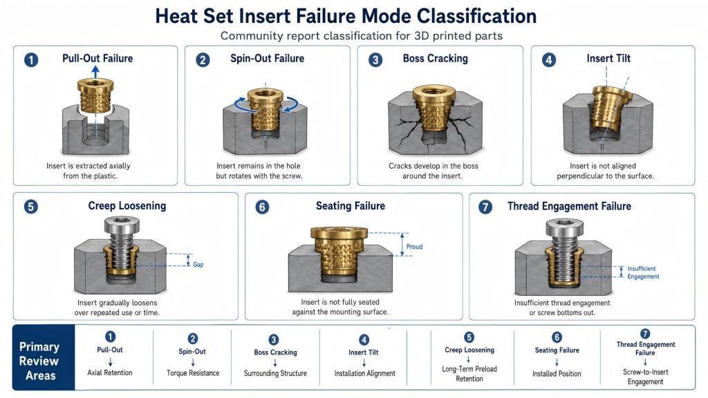
Why Failure Mode Classification Matters
Heat set insert failures are often described with broad phrases such as “the insert failed,” “the hole became loose,” or “the plastic cracked.” These descriptions are not specific enough for engineering analysis.
An insert that pulls out under axial load is not the same as an insert that spins during screw tightening. A boss that cracks during installation is not the same as a PETG joint that loosens over repeated service cycles. Each failure mode points toward a different set of design variables.
For this reason, InsertGuide classifies observed failures before assigning possible root causes.
Primary Failure Modes
The following failure modes should be used as the primary classification categories for future Community Data entries.
| Failure Mode | What Is Observed | Common Variables to Review |
|---|---|---|
| Pull-Out Failure | The insert is extracted from the printed part under axial load. | Insert length, knurl engagement, hole size, material strength, boss depth, and load direction. |
| Spin-Out Failure | The insert rotates inside the plastic when screw torque is applied. | Torque resistance, hole fit, insert knurl geometry, plastic displacement, overheating, and boss support. |
| Boss Cracking | The printed boss splits around the insert during installation, tightening, or service. | Boss OD, wall thickness, edge distance, material brittleness, hole undersizing, and insertion pressure. |
| Insert Tilt | The insert seats at an angle instead of aligning with the screw axis. | Insertion method, guide alignment, hole geometry, uneven heating, and manual press control. |
| Creep Loosening | The joint loses preload or becomes loose over time without immediate fracture. | Material creep, clamp load, temperature, repeated assembly, screw torque, and service duration. |
| Seating Failure | The insert does not fully seat flush or stops before reaching the intended depth. | Hole depth, bottoming, molten plastic flow, insertion temperature, insert length, and blind hole clearance. |
| Thread Engagement Failure | The screw does not achieve enough usable thread engagement or bottoms out. | Screw length, insert depth, hole depth, stack-up, engagement length, and screw selection. |
1. Pull-Out Failure
Pull-out failure occurs when the insert is extracted from the printed part under axial load. The insert may come out with the screw, or it may pull free from the boss when the assembly is loaded.
This failure mode is usually related to the ability of the surrounding plastic to mechanically retain the insert. It should not automatically be blamed on material choice alone.
Typical Observation Clues
- The insert comes out of the boss with the screw.
- The insert is pulled upward from the printed part.
- The surrounding hole appears enlarged or stripped.
- The knurled area may show insufficient plastic engagement.
- The boss may remain mostly intact while the insert is removed.
Variables to Record
- Insert size and length
- Hole diameter
- Hole depth
- Boss wall thickness
- Print orientation
- Material
- Load direction
- Whether the pull was sudden or gradual
2. Spin-Out Failure
Spin-out failure occurs when the insert rotates inside the printed plastic while the screw is tightened, loosened, or loaded in torsion.
This failure mode is primarily related to torque resistance. It is different from pull-out failure because the insert may remain inside the part but lose rotational grip.
Typical Observation Clues
- The screw turns but does not tighten properly.
- The insert rotates with the screw.
- The insert remains seated but loses anti-rotation resistance.
- The plastic around the insert may appear polished, softened, or deformed.
- The failure appears during tightening or removal rather than axial loading.
Variables to Record
- Tightening torque if known
- Insert knurl geometry
- Hole diameter
- Insertion temperature or method
- Material
- Boss OD and support
- Number of assembly cycles
3. Boss Cracking
Boss cracking occurs when the printed boss or surrounding plastic splits around the insert. This may happen during insert installation, screw tightening, or later service.
Boss cracking should be treated as a structural geometry failure, not simply an insert failure. The insert may still be seated, but the surrounding printed structure has lost integrity.
Typical Observation Clues
- A visible crack radiates from the insert hole.
- The boss splits during heat insertion.
- The boss cracks when the screw is tightened.
- The crack follows layer lines or thin wall sections.
- The failure appears near an edge, corner, tab, or unsupported wall.
Variables to Record
- Boss outside diameter
- Wall thickness around the insert
- Edge distance
- Hole size
- Material brittleness
- Print orientation
- Insertion pressure
- Whether cracking occurred during insertion or service
4. Insert Tilt
Insert tilt occurs when the insert is installed at an angle rather than aligned with the intended screw axis. This can cause poor screw engagement, uneven loading, cross-threading, or local stress concentration.
Insert tilt is often caused by installation control rather than material weakness alone.
Typical Observation Clues
- The screw does not enter straight.
- The insert flange or top face is not parallel to the mounting surface.
- The insert appears lower on one side.
- The screw binds before full engagement.
- The joint clamps unevenly.
Variables to Record
- Insertion method
- Whether a guide or jig was used
- Hole diameter
- Hole depth
- Surface flatness
- Insert length
- Whether the part shifted during insertion
5. Creep Loosening
Creep loosening occurs when the joint gradually loses preload or becomes loose over time due to plastic deformation. This is especially important in materials and applications where sustained clamp load, temperature, or repeated assembly cycles are present.
Creep loosening should not be confused with immediate spin-out or pull-out. The insert may remain in place, but the joint no longer holds the intended preload.
Typical Observation Clues
- The screw was initially tight but became loose over time.
- The insert remains seated, but the joint loses clamp force.
- The failure appears after repeated opening and closing.
- The part shows local compression or deformation around the insert.
- The issue appears under sustained load or warm conditions.
Variables to Record
- Material
- Service temperature if known
- Initial tightening torque
- Number of assembly cycles
- Clamp load condition
- Time in service
- Whether the joint was retightened
6. Seating Failure
Seating failure occurs when the insert does not reach the intended installed position. It may sit proud of the surface, stop before full depth, bottom out inside a blind hole, or leave a gap under the insert flange.
Seating failure affects screw engagement, stack-up, clamp load, and alignment.
Typical Observation Clues
- The insert sits above the surface.
- The insert stops before full depth.
- Plastic builds up under the insert flange.
- The insert bottoms out in a blind hole.
- The screw does not reach the expected engagement depth.
Variables to Record
- Insert length
- Hole depth
- Hole bottom shape
- Insertion temperature
- Plastic flow around the insert
- Whether the hole is blind or through-hole
- Final installed position
7. Thread Engagement Failure
Thread engagement failure occurs when the screw does not engage enough thread inside the insert or bottoms out before the joint is properly clamped.
This failure mode is often related to screw length, insert depth, part stack-up, and available engagement length. It may appear as a loose joint even when the insert itself has not failed.
Typical Observation Clues
- The screw feels tight before the parts are clamped.
- The screw bottoms out inside the insert or blind hole.
- The joint remains loose even after tightening.
- The screw engagement length is shorter than expected.
- The insert appears properly installed but the assembly still fails to clamp.
Variables to Record
- Screw length
- Insert internal thread depth
- Installed insert depth
- Part stack-up thickness
- Washer or bracket thickness
- Blind hole clearance
- Thread engagement length
Secondary Failure Descriptors
Some observations may need a secondary descriptor in addition to the primary failure mode. These descriptors help describe the condition more accurately.
| Secondary Descriptor | Meaning |
|---|---|
| During Insertion | The failure occurred while installing the insert. |
| During Tightening | The failure occurred while tightening the screw. |
| During Removal | The failure occurred while removing the screw. |
| After Repeated Cycles | The failure appeared after multiple screw installation and removal cycles. |
| Under Vibration | The failure appeared in a vibrating assembly. |
| Under Sustained Load | The failure appeared after the joint remained loaded over time. |
| Near Edge or Corner | The insert was placed close to a free edge, corner, tab, slot, or unsupported wall. |
How to Classify a Community Report
When reviewing a community report, forum post, repair note, or workshop observation, classify the failure in this order:
- Identify the visible failure mode.
- Record whether it happened during insertion, tightening, removal, service, or repeated cycling.
- Record the known material, insert size, and hole geometry.
- Mark unknown fields as unknown instead of guessing.
- Assign an evidence level.
- Only then interpret possible root causes.
This sequence keeps the report factual before it becomes analytical.
Common Classification Mistakes
Failure reports become less useful when different failure modes are mixed together. InsertGuide avoids the following mistakes in Community Data entries:
- Calling every loose insert a pull-out failure.
- Calling every tightening problem a torque problem.
- Blaming PETG or PLA before checking hole size and boss geometry.
- Treating boss cracking as the same problem as insert spin-out.
- Assuming a tilted insert is caused by weak material.
- Ignoring screw bottoming when the joint fails to clamp.
- Calling a repeated service issue an installation issue without evidence.
Connecting Failure Modes to Design Variables
Each failure mode points toward a different part of the fastening system. The table below shows how the failure classification connects to likely design review areas.
| Failure Mode | Primary Review Area | Related Design Variables |
|---|---|---|
| Pull-Out Failure | Axial retention | Insert length, hole size, knurl engagement, boss depth, and material strength. |
| Spin-Out Failure | Torque resistance | Knurl geometry, hole fit, screw torque, plastic flow, and boss support. |
| Boss Cracking | Surrounding structure | Boss OD, wall thickness, edge distance, material brittleness, and insertion pressure. |
| Insert Tilt | Installation alignment | Insertion method, guide control, hole straightness, and seating pressure. |
| Creep Loosening | Long-term preload retention | Material creep, sustained load, temperature, assembly cycles, and clamp force. |
| Seating Failure | Installed position | Hole depth, insert length, molten plastic flow, bottoming, and surface flushness. |
| Thread Engagement Failure | Screw-to-insert engagement | Screw length, insert depth, stack-up, blind hole clearance, and usable thread length. |
Relationship to Community Data Evidence Levels
Failure mode classification does not decide evidence strength by itself. A report can correctly identify spin-out failure but still remain an unverified anecdote if the report lacks hole size, material, torque, or insert details.
Classification answers the question: what failed?
Evidence level answers the question: how strongly can this report support an engineering conclusion?
Both are needed for useful Community Data.
Related Community Data Standards
- Community Engineering Data Collection Standard for Heat Set Inserts
- Heat Set Insert Failure Observation Report Template
Related Engineering Guides
- Heat Set Insert Hole Size Guide
- How to Design Bosses for Heat Set Inserts
- Pull-Out Strength of Heat Set Inserts in 3D Printed Parts
- Torque Resistance of Heat Set Inserts in 3D Printed Parts
- Screw Engagement Length for Heat Set Inserts in 3D Printed Parts
- PLA vs PETG vs ABS for Threaded Inserts
Conclusion
The Heat Set Insert Failure Mode Classification Guide for Community Reports provides a consistent way to describe observed insert failures before interpreting their causes.
By separating pull-out failure, spin-out failure, boss cracking, insert tilt, creep loosening, seating failure, and thread engagement failure, future Community Data entries can become more precise, more comparable, and more useful for engineering diagnosis.