
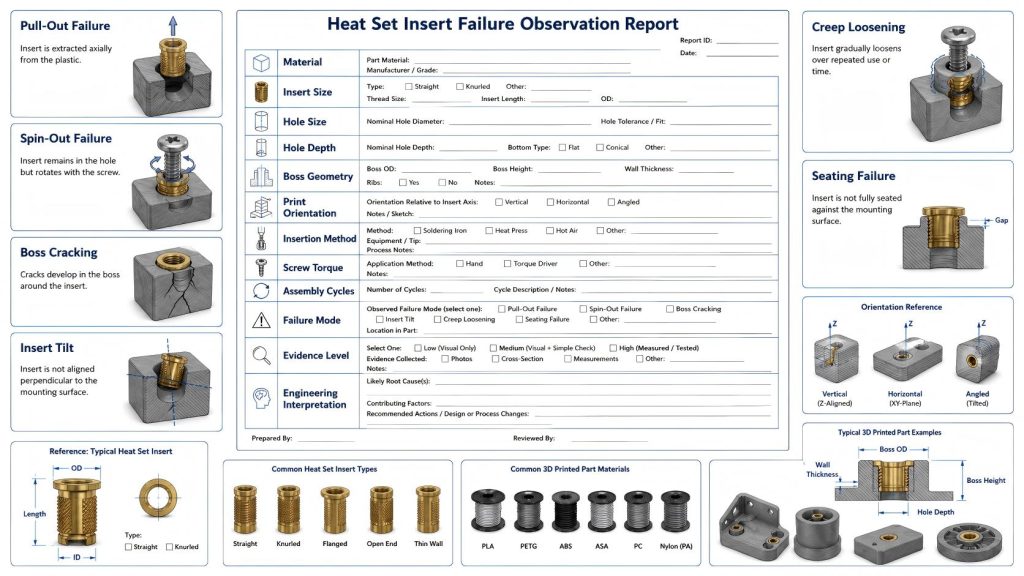
Heat Set Insert Failure Observation Report Template defines the standard field structure used by InsertGuide to record heat set insert failure observations in 3D printed parts.
This page is not a test result page. It does not claim that a specific material, hole size, insert type, or boss design has already failed. Instead, it provides a repeatable reporting format for future community engineering data entries.
The purpose of this template is to make failure observations clearer, more comparable, and easier to connect with engineering variables such as material behavior, pilot hole size, boss geometry, print orientation, screw torque, and repeated assembly cycles.
Why a Failure Observation Template Is Needed
Heat set insert failures are often described casually: an insert came loose, a boss cracked, a screw stripped, or a printed part failed after repeated use. These observations can be useful, but only if the technical context is recorded.
Without a consistent report structure, it is difficult to know whether a failure was caused by the insert, the printed material, the hole size, the boss design, the installation process, the screw load, or the way the assembly was used.
This template helps separate what was observed from what may have caused the failure.
How This Template Should Be Used
Each future Community Data entry should use this template as a base structure. If a detail is unknown, it should be marked as unknown. Missing information should not be guessed.
A useful failure observation report should answer three questions:
- What exactly failed?
- What design and assembly conditions were present?
- What can be interpreted cautiously from the observation?
The report should not turn a single case into a universal design rule.
Failure Observation Report Fields
| Field | Required Information | Notes |
|---|---|---|
| Observation Title | A short title describing the failure. | Example format: Insert spin-out in PETG enclosure boss. Do not include unsupported conclusions. |
| Observation Type | Field report, repair note, test coupon, repeated report pattern, forum summary, or controlled test. | This helps separate casual observations from stronger evidence. |
| Evidence Level | Unverified anecdote, observed report, repeated report pattern, controlled test, or engineering interpretation. | The evidence level should match the available detail. |
| Source Type | Workshop note, user submission, forum post, Reddit report, maker log, service repair, or internal test. | Do not treat all source types as equal. |
| Material | PLA, PETG, ABS, ASA, nylon, polycarbonate, resin, or other material. | Material behavior strongly affects cracking, creep, and heat response. |
| Insert Size | M2, M2.5, M3, M4, M5, or another thread size. | Insert size affects pilot hole, boss diameter, heat transfer, and load capacity. |
| Insert Type | Heat set insert, press-fit insert, expansion insert, molded insert, or unknown. | Different insert structures fail differently. |
| Hole Size | Printed pilot hole diameter if known. | Mark as unknown if no measurement is available. |
| Hole Depth | Measured blind hole depth, through-hole condition, or unknown. | Insufficient depth can cause seating or bottoming problems. |
| Boss Outside Diameter | Measured boss OD or estimated from CAD if known. | This is important for cracking and wall support evaluation. |
| Boss Wall Thickness | Wall thickness around the insert if known. | Thin walls increase cracking and deformation risk. |
| Edge Distance | Distance from insert centerline or outer edge to the nearest part edge. | Low edge distance can reduce structural support. |
| Print Orientation | Insert axis relative to layer direction. | Layer orientation can affect splitting, pull-out, and local stiffness. |
| Layer Height and Print Settings | Layer height, wall count, infill, and nozzle size if known. | These details are useful but should not be invented. |
| Insertion Method | Soldering iron, heat press, ultrasonic tool, manual press, or unknown. | Installation method may affect alignment and plastic flow. |
| Insertion Temperature | Measured temperature if available. | Do not guess temperature from tool settings unless stated clearly. |
| Insertion Depth | Flush, proud, recessed, tilted, bottomed out, or unknown. | Improper seating can affect screw engagement and joint behavior. |
| Screw Size | Thread size and screw length. | Screw length affects engagement and bottoming risk. |
| Screw Engagement Length | Approximate thread engagement length if known. | Too little engagement can weaken the joint; too much may cause bottoming. |
| Tightening Torque | Measured torque, torque driver setting, hand-tight description, or unknown. | Qualitative torque descriptions should be labeled as qualitative. |
| Assembly Cycles | Number of screw installation and removal cycles if known. | Repeated assembly can reveal progressive loosening or material creep. |
| Load Condition | Static clamp load, vibration, hinge load, pull load, shear load, service access, or unknown. | Failure meaning changes depending on load type. |
| Observed Failure Mode | Pull-out, spin-out, boss cracking, insert tilt, creep loosening, seating failure, or thread engagement failure. | Use the observed failure mode before interpreting cause. |
| Observation Summary | A short factual summary of what happened. | Describe the observation without overstating the cause. |
| Possible Root Causes | Possible contributing variables. | Use cautious language unless the cause is directly supported. |
| Related Design Variable | Hole size, boss geometry, edge distance, torque, material creep, insertion depth, or screw engagement. | This connects the report to engineering structure. |
| Engineering Interpretation | A cautious explanation of what the observation may suggest. | Separate interpretation from the raw observation. |
| Confidence Level | Low, medium, or high. | Confidence depends on detail, repeatability, and measurement quality. |
| Related InsertGuide Links | Relevant guides, references, or failure questions. | Use links to connect the observation to the wider engineering knowledge map. |
Recommended Report Structure
A future heat set insert failure observation should follow this structure:
1. Observation Summary
Describe what was seen. Do not explain the cause yet.
- What failed?
- When did it fail?
- Was the failure during insertion, tightening, service, vibration, or repeated disassembly?
- Was the insert pulled out, rotated, tilted, loosened, or surrounded by cracked plastic?
2. Part and Material Context
Record the printed part conditions that may influence the result.
- Material
- Print orientation
- Layer height if known
- Wall count if known
- Infill if relevant
- Part function or application context
3. Insert and Hole Details
Record the fastening geometry. These fields are often more important than the broad application category.
- Insert size
- Insert type
- Pilot hole diameter
- Hole depth
- Insert seating depth
- Whether the hole was blind or through-hole
4. Boss and Surrounding Geometry
Record the geometry around the insert. A failure in a thin boss is different from a failure in a well-supported structural block.
- Boss outside diameter
- Wall thickness around the insert
- Edge distance
- Nearby ribs, walls, or unsupported corners
- Whether the insert sits near a part edge, hinge, slot, or mounting tab
5. Assembly and Loading Conditions
Record how the joint was used and loaded.
- Screw size and length
- Estimated or measured tightening torque
- Number of assembly cycles
- Vibration exposure
- Pull load, clamp load, hinge load, or shear load
- Whether the part was opened frequently for service
6. Failure Classification
Classify the observed failure before identifying possible causes.
- Pull-out failure
- Spin-out failure
- Boss cracking
- Insert tilt
- Creep loosening
- Seating failure
- Thread engagement failure
7. Evidence Level
Assign the correct evidence level. A single report should not be presented as a tested rule.
- Unverified anecdote
- Observed report
- Repeated report pattern
- Controlled test
- Engineering interpretation
8. Engineering Interpretation
Interpret the observation only after the raw fields have been recorded.
A good interpretation should say what the observation may suggest, what variables are missing, and which design areas may require review.
For example, a spinning insert may suggest a torque resistance issue, but the actual cause may involve pilot hole size, knurl engagement, insufficient plastic displacement, overheating, low boss support, or excessive screw torque.
Example Blank Report Format
The following blank format can be reused for future Community Data entries.
| Report Field | Entry |
|---|---|
| Observation Title | |
| Observation Type | |
| Evidence Level | |
| Source Type | |
| Material | |
| Insert Size | |
| Insert Type | |
| Hole Size | |
| Hole Depth | |
| Boss Outside Diameter | |
| Boss Wall Thickness | |
| Edge Distance | |
| Print Orientation | |
| Insertion Method | |
| Insertion Temperature | |
| Insertion Depth | |
| Screw Size and Length | |
| Screw Engagement Length | |
| Tightening Torque | |
| Assembly Cycles | |
| Load Condition | |
| Observed Failure Mode | |
| Observation Summary | |
| Possible Root Causes | |
| Engineering Interpretation | |
| Confidence Level | |
| Related InsertGuide Links |
How to Avoid Overstating a Failure Report
A heat set insert failure report should not claim more than the observation supports. The difference between observation and interpretation must remain visible.
- Write what happened before explaining why it may have happened.
- Do not guess missing hole size, torque, or temperature values.
- Do not turn one failed part into a universal material rule.
- Do not assume the material was the only cause.
- Do not treat hand-tightening descriptions as measured torque data.
- Do not present forum comments as controlled test results.
- Do not remove uncertainty from the report.
How This Template Supports Future Community Data
This template gives future Community Data entries a consistent structure. Over time, repeated reports can reveal patterns that are difficult to see from isolated observations.
For example, multiple reports of PETG insert loosening under repeated assembly may suggest a creep-related pattern. Multiple reports of PLA boss cracking during installation may point toward boss wall thickness, pilot hole fit, insertion pressure, or local brittleness.
However, these patterns should still be treated carefully. A repeated report pattern is stronger than a single anecdote, but it is not the same as a controlled test.
Related Engineering Guides
- Heat Set Insert Hole Size Guide
- How to Design Bosses for Heat Set Inserts
- Pull-Out Strength of Heat Set Inserts in 3D Printed Parts
- Torque Resistance of Heat Set Inserts in 3D Printed Parts
- Screw Engagement Length for Heat Set Inserts in 3D Printed Parts
- PLA vs PETG vs ABS for Threaded Inserts
Related Engineering References
- Heat Set Insert Torque Range Reference
- Heat Set Insert Edge Distance Reference
- Heat Set Insert Minimum Wall Thickness Reference
- Heat Set Insert Pilot Hole Tolerance Reference
- Heat Set Insert Seating Depth Reference
Conclusion
The Heat Set Insert Failure Observation Report Template provides a consistent structure for recording future community engineering data. It helps keep field observations, test conditions, missing variables, failure classifications, and engineering interpretation separate.
This makes Community Data more useful, more transparent, and less likely to overstate what a single observation can prove.
Related Decision Resources
For insert selection, tool choice, and supplier comparison, use these decision-focused references after the engineering requirements are defined.