
M5 heat set insert installation requires more control than smaller insert sizes because the insert is larger, the pilot hole removes more plastic, the installation process needs more heat, and the printed boss must absorb greater insertion pressure without cracking, tilting, or softening excessively.
M5 inserts are often used in stronger printed brackets, fixtures, equipment mounts, larger housings, and functional assemblies where the screw connection needs more clamping capacity than M3 or M4. However, M5 is also large enough to damage a printed boss if the hole size, heat input, insertion pressure, seating depth, or boss geometry is not controlled.
This guide explains the key installation variables for M5 heat set inserts in 3D printed parts, including pilot hole fit, soldering iron temperature, insertion alignment, seating depth, boss base support, material behavior, and common installation failure modes.
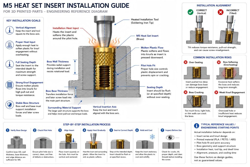
Engineering Overview
Installing an M5 heat set insert is not simply a matter of melting brass into plastic. The goal is to soften enough material around the pilot hole so the insert knurls can displace and engage the plastic without destroying the boss structure.
Compared with smaller inserts, an M5 insert usually requires more heat energy and more vertical control. The insert has a larger outside diameter, larger thermal mass, and greater contact area with the printed boss. If the insert is pushed too aggressively, the boss may bulge, crack, or deform. If the insert is overheated, the plastic around the boss may lose shape and reduce long-term torque resistance. If the insert is underheated, it may not seat fully or may drag plastic downward instead of forming clean knurl engagement.
For M5 inserts, installation quality strongly affects later pull-out strength, torque resistance, screw alignment, and repeated assembly performance.
Typical Reference Factors for M5 Insert Installation
The table below provides typical reference values and engineering starting points. These are not universal process settings. Actual installation behavior depends on insert series, insert outside diameter, knurl geometry, printed material, print orientation, soldering iron tip geometry, installation temperature, and part design.
| Installation Variable | Engineering Purpose | Risk if Poorly Controlled | Design Note |
|---|---|---|---|
| Insert Size | M5 provides larger screw capacity and deeper insert engagement | Larger insert can overheat or distort the boss if installed carelessly | M5 should be installed as a structural fastening feature, not as a small hardware detail. |
| Pilot Hole Fit | Guides insert entry and controls plastic displacement into the knurls | Oversized holes reduce retention; tight holes can crack or bulge the boss | Use insert manufacturer data and adjust based on printed material behavior. |
| Installation Heat | Softens plastic around the insert enough for controlled seating | Too much heat causes sinking, softening, tilt, or boss deformation | Larger M5 inserts need more heat energy but not uncontrolled overheating. |
| Insertion Pressure | Moves the insert vertically into the softened pilot hole | Excess force can split the boss or push the insert off-axis | The insert should sink gradually under heat, not be forced into cold plastic. |
| Seating Depth | Ensures full insert engagement and stable screw support | Shallow seating reduces strength; over-seating can damage the boss base | The insert should sit flush or at the intended depth without bottoming out. |
| Screw Axis Alignment | Keeps the insert vertical and aligned with the mating part | Misalignment creates insert tilt, side loading, and uneven knurl engagement | M5 inserts magnify alignment errors because the screw and insert are larger. |
| Boss Wall Thickness | Supports radial expansion during installation | Thin boss walls may crack, bulge, or soften around the insert | M5 bosses need generous wall support and enough distance from edges. |
| Boss Base Thickness | Supports the insert after seating and transfers screw load into the part | A weak base may deform when the insert is pressed or later tightened | Installation should not crush or overheat the base below the insert. |
| Cooling Time | Allows plastic to solidify around the insert before loading | Moving or tightening too soon can shift the insert or weaken engagement | Do not load the insert while the surrounding plastic is still soft. |
Recommended Installation Rules
- Start with the correct pilot hole. The pilot hole should match the insert series and printed material. An easy installation is not always a strong installation if the hole is oversized.
- Use a flat or insert-compatible heated tip. The tool should apply heat evenly to the top of the insert without slipping into the internal thread or pushing the insert off-axis.
- Keep the insert vertical during seating. M5 inserts are large enough that a small tilt can create serious screw alignment problems later.
- Let heat do the work. The insert should gradually sink as the plastic softens. Forcing it into the hole can crack the boss or distort the base.
- Stop at the intended seating depth. Over-seating can crush the boss base or leave the insert below the surface in a way that affects assembly stack-up.
- Avoid excessive heat soak. M5 inserts need more heat energy than smaller inserts, but too much dwell time can soften the entire boss and reduce retention.
- Allow the boss to cool before tightening a screw. Loading the insert while the plastic is still soft can cause movement, tilt, or weak knurl engagement.
- Check whether the boss is large enough before installation. If the printed boss has thin walls, poor edge distance, or a weak base, careful installation may not fully solve the structural problem.
Material Adjustments for PLA, PETG, and ABS
PLA
PLA is stiff and can hold a crisp insert interface when the installation process is controlled. However, it is brittle and sensitive to excessive radial stress. For M5 heat set inserts, PLA bosses can crack if the pilot hole is too tight, the insert is forced downward, or the boss wall is too thin.
When installing M5 inserts in PLA, use controlled heat and avoid treating the insert like a press-fit part. The insert should melt into the plastic gradually. If the boss begins to split or whiten around the insert, the hole fit, heat input, or boss geometry is likely too aggressive.
PETG
PETG is tougher than PLA and usually tolerates insertion stress better. It can deform rather than crack, which can be useful during installation. However, PETG can become stringy or overly soft if heat is applied for too long.
For M5 inserts in PETG, the main risk is local deformation and long-term creep. A clean installation should avoid overheating the boss and should leave enough surrounding plastic support for later screw tightening. PETG may feel forgiving during installation but still lose preload stability if the boss is undersized.
ABS
ABS can handle heat better than PLA in many practical applications, but installation control still matters. M5 inserts require enough heat to engage the knurls, yet excessive heat can soften the boss and reduce shape accuracy.
For ABS, avoid letting the insert sink too deeply or tilt while the plastic is soft. The boss should cool before any screw preload is applied. Print quality and layer adhesion also matter because M5 installation can transmit heat and pressure into a larger volume of plastic.
Step-by-Step M5 Installation Process
1. Verify the Boss Design
Before installing the insert, confirm that the boss has enough outside diameter, wall thickness, base thickness, and edge distance. M5 inserts should not be installed into a boss that is only slightly larger than the insert outside diameter.
2. Check the Pilot Hole
The pilot hole should be sized for the specific insert series and printed material. If the insert drops in loosely before heating, torque resistance and pull-out strength may be reduced. If the insert cannot start straight, the hole may be too tight or poorly printed.
3. Align the Insert
Place the insert squarely over the pilot hole. The insert axis should match the boss axis and expected screw path. Alignment is especially important for M5 because the screw will apply higher torque and side load if the insert is tilted.
4. Apply Heat Gradually
Use a heated tool to warm the insert and soften the plastic around the pilot hole. Avoid pushing hard before the plastic begins to flow. The insert should move downward in a controlled way as heat transfers through the brass body.
5. Seat the Insert to the Correct Depth
Stop when the insert reaches the intended seating depth. In many designs, the insert is flush with the boss top surface, but some assemblies may require a slight recess depending on screw stack-up and mating part geometry.
6. Hold Position During Cooling
Keep the insert aligned while the plastic cools enough to stabilize. Avoid twisting, pulling, or loading the insert during this period. Movement during cooling can reduce knurl engagement and create tilt.
7. Inspect Before Assembly
After cooling, inspect the boss for cracks, bulging, sinking, tilt, or plastic buildup around the insert. If the screw does not enter smoothly, do not force it. Misalignment or thread contamination may damage the joint.
Common Installation Failure Modes
Installation defects should be checked against M5 heat set insert failure modes.
1. Insert Tilt
Insert tilt occurs when the insert is pushed at an angle, the soldering iron tip slips, or the pilot hole does not guide the insert straight. Tilt reduces screw alignment and can weaken both torque resistance and pull-out strength.
2. Boss Cracking During Installation
Boss cracking usually means the pilot hole was too tight, the boss wall was too thin, the insert was forced downward too aggressively, or the material was too brittle. PLA is especially sensitive to this failure mode.
3. Over-Seating
Over-seating happens when the insert is pushed too deep or when excessive heat softens the boss base. This can reduce effective screw engagement, damage the boss base, or create an uneven assembly surface.
4. Local Plastic Bulging
Bulging occurs when displaced plastic has nowhere to flow or when the boss wall is too thin to contain expansion. In M5 installations, this can also indicate that the boss OD is too small for the insert size.
5. Weak Knurl Engagement
Weak knurl engagement can result from an oversized pilot hole, insufficient heat, poor insert geometry, or moving the insert during cooling. The insert may look seated but later spin or pull out under screw load.
6. Boss Softening and Shape Loss
Large inserts require more heat energy. If heat is applied for too long, the entire boss can soften and lose shape. This is especially risky for compact bosses, PETG parts under preload, or ABS parts with poor cooling control.
Why M5 Installation Is Different from Smaller Inserts
M5 inserts are not simply larger versions of M3 or M4 inserts. They require more thermal control, more boss volume, and more careful alignment. The larger insert can heat a wider zone of plastic, and the larger screw can later apply more torque and preload.
Small installation errors that may be acceptable in M3 can become serious in M5. A slight tilt, a shallow seating depth, a softened boss base, or weak edge distance can create a fastening joint that appears strong but fails when tightened or serviced.
M5 should be selected when the printed part has enough material structure to support it. If the geometry is compact, thin, or close to an edge, an M4 insert or redesigned fastening structure may be more reliable.
When M5 Installation Risk Is High
- The boss wall is thin relative to the insert outside diameter.
- The boss is close to an edge, corner, slot, or cutout.
- The pilot hole is inconsistent because of print shrinkage or poor calibration.
- The insert requires high heat and the material softens easily.
- The insert is installed by hand without a vertical guide.
- The screw will be tightened strongly after installation.
- The boss base is shallow or poorly connected to the main printed body.
Related Engineering Guides
- M5 Heat Set Insert Dimensions Reference for 3D Printed Parts
- M5 Heat Set Insert Hole Size for 3D Printed Parts
- M5 Heat Set Insert Boss Design for 3D Printed Parts
- M5 Heat Set Insert Pull-Out Strength for 3D Printed Parts
- M5 Heat Set Insert Torque Resistance for 3D Printed Parts
- Heat Set Insert Installation Temperature for 3D Printed Parts
- Heat Set Insert Pilot Hole Tolerance Reference for 3D Printed Parts
- Heat Set Insert Seating Depth Reference for 3D Printed Parts
- Heat Set Insert Hole Depth Chart for 3D Printed Parts
- PLA vs PETG vs ABS for Threaded Inserts
FAQ
What makes M5 heat set insert installation different from M3 or M4?
M5 inserts are larger and require more heat energy, more boss support, and better alignment control. The larger screw can also apply more tightening torque after installation, so small installation errors can create larger structural problems.
Why does an M5 heat set insert tilt during installation?
Insert tilt usually happens when the heated tool is not vertical, the pilot hole does not guide the insert properly, the insert is pushed before the plastic softens, or the boss geometry is uneven. Tilt can reduce torque resistance and pull-out strength.
Should an M5 heat set insert be flush with the boss surface?
In many designs, the insert is seated flush with the boss top surface, but the correct seating depth depends on the insert length, hole depth, screw engagement, and mating part stack-up. The insert should not bottom out or sink unpredictably into the boss base.
Can too much heat weaken an M5 heat set insert joint?
Yes. Excessive heat can soften the boss, smear the plastic around the knurls, cause the insert to sink or tilt, and reduce long-term retention. M5 inserts need enough heat for plastic flow, but not uncontrolled heat soak.
When should I avoid installing M5 inserts in a printed part?
Avoid M5 inserts when the boss cannot provide enough wall thickness, base thickness, edge distance, or surrounding part support. If the printed geometry is too compact, M4 or a redesigned fastening structure may be more reliable.
Related Decision Resources
For insert selection, tool choice, and supplier comparison, use these decision-focused references after the engineering requirements are defined.