
M2.5 heat set insert pull-out strength depends on how well the insert, pilot hole, boss geometry, material behavior, and screw load path work together inside a 3D printed part.
An M2.5 insert is often used when a design needs more fastening strength than M2 but still cannot afford the space required by M3. This makes pull-out strength especially important in compact electronics housings, sensor brackets, service covers, small fixtures, and lightweight printed assemblies where the boss has limited surrounding plastic.
This article explains the main design variables that affect M2.5 heat set insert pull-out strength in 3D printed parts, including hole size, insert depth, boss support, wall thickness, layer orientation, material choice, and repeated assembly behavior.
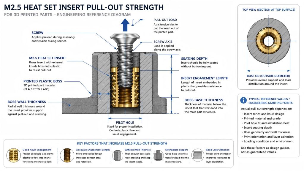
Engineering Overview
Pull-out strength describes the resistance of a heat set insert against being pulled out of the printed plastic along the screw axis. In practice, this load may come from screw preload, external tension, service removal, panel separation, vibration, impact, or repeated disassembly.
For M2.5 inserts, the available contact area is larger than M2 but still much smaller than M3. This means small errors in pilot hole fit, seating depth, boss wall thickness, or material selection can have a noticeable effect on retention. A joint may feel secure during the first assembly but lose strength after repeated tightening cycles if the plastic around the insert creeps, cracks, or deforms.
M2.5 pull-out strength should not be evaluated only by thread size. The insert outside diameter, knurl engagement, embedded length, boss geometry, print material, and load direction are usually more important than the nominal M2.5 screw size itself.
Typical Reference Factors for M2.5 Pull-Out Strength
The following table provides engineering starting points for evaluating M2.5 heat set insert pull-out strength. These are not universal test values. Actual pull-out performance depends on the insert series, printed material, print orientation, pilot hole tolerance, insertion temperature, boss geometry, and loading condition.
| Design Variable | Effect on Pull-Out Strength | Risk if Poorly Controlled | Engineering Note |
|---|---|---|---|
| Insert Size | M2.5 provides more embedded surface area than M2 but less than M3 | Using M2.5 in a high-load joint may exceed the available plastic retention area | Good for compact serviceable joints, not ideal for heavy structural tension loads. |
| Insert Outside Diameter | Larger OD increases plastic engagement area around the insert | A small OD insert may have limited knurl engagement in weak materials | Pull-out strength should be considered from insert OD and embedded length, not thread size alone. |
| Pilot Hole Fit | Controls how much plastic flows into the insert knurls during installation | Oversized holes reduce retention; tight holes can crack the boss | The best pull-out result usually comes from controlled plastic displacement, not extreme interference. |
| Seating Depth | More complete seating improves engagement along the insert length | Shallow seating reduces contact area and may cause early pull-out | The insert should sit fully without bottoming out or damaging the boss base. |
| Boss Wall Thickness | Supports the plastic around the insert under axial load | Thin boss walls may crack, deform, or split during loading | Wall support is especially important when M2.5 inserts are used near edges or thin covers. |
| Boss Base Thickness | Transfers insert load into the larger printed part | A weak base can deform or tear even if the insert itself is seated correctly | Pull-out failure can occur below the insert, not only around the knurls. |
| Layer Orientation | Determines whether pull-out load works with or against layer adhesion | Poor orientation can cause layer separation around the boss | Design the boss and print direction so the load path is not dependent on weak layer separation resistance. |
| Material | Controls stiffness, creep resistance, toughness, and heat response | PLA may crack; PETG may relax; ABS may deform if overheated | Material behavior changes both installation quality and long-term retention. |
Recommended Design Rules
- Evaluate pull-out strength from the full insert geometry. M2.5 thread size does not define retention by itself. Insert OD, embedded length, knurl form, and plastic engagement control the actual load path.
- Use a pilot hole that allows controlled plastic flow. If the hole is too large, the insert may not grip enough plastic. If the hole is too tight, the boss may crack before the insert develops proper retention.
- Seat the insert fully but avoid bottoming out. A shallow insert reduces engagement length. A hole that is too shallow may force the insert against the boss base and create deformation or tilt.
- Design the boss as part of the pull-out system. The boss outside diameter, wall thickness, and base thickness all affect how the insert load spreads into the printed part.
- Increase support near edges and thin walls. M2.5 inserts used close to part edges are more likely to pull out with surrounding plastic damage instead of clean insert movement.
- Match the insert size to the service load. M2.5 is useful for compact serviceable joints, but high-tension or high-vibration joints may require M3 or a larger fastening structure.
- Consider repeated assembly, not only first-use strength. Pull-out resistance can degrade when the boss experiences preload cycles, heat exposure, material creep, or screw misalignment.
Material Adjustments for PLA, PETG, and ABS
PLA
PLA is stiff and dimensionally stable, which can help the insert feel secure after installation. However, PLA is also more brittle than PETG and may crack if the pilot hole is too tight or the boss wall is too thin.
For M2.5 pull-out strength in PLA, the main design risk is not only insert retention but also boss fracture. A PLA boss can fail by cracking around the insert before the insert cleanly pulls out. Good PLA design should use enough boss wall thickness, controlled insertion temperature, and a pilot hole that does not create excessive radial stress.
PETG
PETG is tougher and more ductile than PLA, so it often tolerates heat-set installation better. However, PETG can relax under sustained screw preload, especially in warm environments or when the boss is undersized.
For M2.5 inserts in PETG, pull-out strength should be considered together with long-term creep. A joint may pass an initial hand-tightening check but lose clamping force or retention after repeated assembly. PETG bosses usually benefit from conservative wall thickness, adequate insert depth, and reduced side loading.
ABS
ABS can be useful for functional parts because it handles heat and impact better than PLA in many situations. However, ABS boss performance depends strongly on print quality, layer bonding, and installation heat control.
For M2.5 pull-out strength in ABS, overheating the insert can soften the boss excessively and reduce local retention. A controlled installation process and stable seating depth are important because a tilted or sunken insert may reduce effective engagement and weaken the load path.
Common Pull-Out Failure Modes
Pull-out behavior should be reviewed together with M2.5 torque resistance.
1. Insert Pulls Out Cleanly
This failure occurs when the insert separates from the surrounding plastic without major boss cracking. It usually indicates poor knurl engagement, an oversized pilot hole, insufficient seating depth, or inadequate embedded length.
2. Boss Cracks Around the Insert
In this failure mode, the boss splits before the insert can carry the expected axial load. It is common when the boss wall is too thin, the insert is too close to an edge, or the pilot hole creates excessive installation stress. PLA is especially vulnerable to this pattern.
3. Plastic Tears Below the Insert
Sometimes the insert itself remains engaged, but the boss base or surrounding printed structure tears away. This means the weak point is not the insert interface but the load path below the insert. Boss base thickness and part geometry are important for preventing this failure.
4. Pull-Out After Repeated Assembly
An M2.5 insert may survive the first installation and first screw assembly but loosen after repeated service cycles. This is often caused by material creep, thread preload relaxation, screw misalignment, or gradual damage to the plastic around the knurls.
5. Tilted Insert Reduces Retention
If the insert is installed at an angle, one side of the knurl may engage more deeply than the other. This creates uneven stress under screw load and can reduce pull-out strength. Small M2.5 bosses are less forgiving of alignment errors than larger bosses.
Why M2.5 Pull-Out Strength Is Different from M2 and M3
M2.5 offers a useful middle ground between M2 and M3. Compared with M2, it gives more insert surface area, better screw handling, and a larger boss structure. This usually improves pull-out behavior in compact service parts.
Compared with M3, M2.5 still has less embedded area and less surrounding boss volume. This makes the joint more sensitive to edge distance, seating depth, pilot hole fit, and material creep. M2.5 can be a good design choice, but it should not be treated as a miniature version of an M3 structural joint.
When M2.5 Pull-Out Strength Is Usually Enough
- Small electronics covers that are opened occasionally
- Sensor brackets with light service loads
- Compact printed housings where M3 bosses are too large
- Low-to-moderate screw preload applications
- Parts where boss OD, wall thickness, and edge distance can still be properly controlled
When M2.5 May Not Be Enough
- High-tension joints that pull directly on the insert
- Parts exposed to frequent vibration or impact
- Very thin printed covers with limited boss height
- Bosses located too close to corners or cutouts
- Repeated service joints where screw preload must remain stable over many cycles
Related Engineering Guides
- M2.5 Heat Set Insert Dimensions Reference for 3D Printed Parts
- M2.5 Heat Set Insert Hole Size for 3D Printed Parts
- M2.5 Heat Set Insert Boss Design for 3D Printed Parts
- Pull-Out Strength of Heat Set Inserts in 3D Printed Parts
- Heat Set Insert Minimum Wall Thickness Reference for 3D Printed Parts
- Heat Set Insert Edge Distance Reference for 3D Printed Parts
- Heat Set Insert Seating Depth Reference for 3D Printed Parts
- PLA vs PETG vs ABS for Threaded Inserts
FAQ
What affects M2.5 heat set insert pull-out strength the most?
The most important factors are insert outside diameter, embedded length, pilot hole fit, seating depth, boss wall thickness, boss base support, material behavior, and print orientation. Thread size alone does not define pull-out strength.
Is M2.5 stronger than M2 for pull-out resistance?
In most compact printed parts, M2.5 provides better pull-out potential than M2 because it usually has more insert surface area and more boss volume. However, the actual result still depends on the insert design, boss geometry, and printed material.
Can an M2.5 heat set insert pull out even if the boss does not crack?
Yes. A clean pull-out can happen when the pilot hole is oversized, the insert is seated too shallow, the knurl engagement is weak, or the plastic relaxes around the insert after repeated assembly.
Does PETG improve M2.5 pull-out strength?
PETG can improve toughness during installation, but it may relax under sustained preload. PETG does not automatically guarantee better long-term pull-out resistance unless the boss has enough wall support and proper insert engagement.
When should I use M3 instead of M2.5 for pull-out strength?
Use M3 when the joint carries higher tension, repeated service loads, vibration, or structural load. M2.5 is useful for compact parts, but M3 usually provides more boss volume and insert engagement for stronger load paths.
Related Decision Resources
For insert selection, tool choice, and supplier comparison, use these decision-focused references after the engineering requirements are defined.