
M2.5 heat set insert torque resistance depends on how well the insert knurls, pilot hole, boss geometry, wall thickness, printed material, and screw preload work together to prevent the insert from rotating inside a 3D printed boss.
An M2.5 insert is often chosen when M2 feels too small for repeated fastening but M3 takes too much space. This makes torque resistance a critical design factor in compact electronics housings, sensor brackets, small covers, lightweight service panels, and printed assemblies where the screw may be tightened and removed multiple times.
This article explains the main engineering variables that affect M2.5 heat set insert torque resistance in 3D printed parts, including pilot hole fit, boss support, insert engagement, material behavior, screw alignment, and common spin-related failure modes.
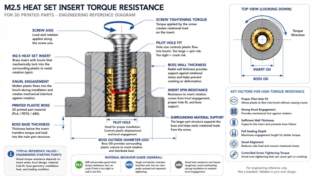
Engineering Overview
Torque resistance describes the ability of a heat set insert to resist rotation when a screw is tightened, loosened, or loaded in service. For heat set inserts in 3D printed parts, torque resistance is mainly created by the mechanical engagement between the insert knurls and the surrounding printed plastic.
For M2.5 inserts, torque resistance is more forgiving than M2 because the insert has more outside surface area and usually more boss volume. However, it is still less forgiving than M3 because the boss wall, edge distance, and insert engagement area remain compact. A small change in pilot hole fit, heat input, wall thickness, or screw alignment can noticeably affect whether the insert stays locked or begins to spin.
Torque resistance should not be judged only by the screw size. The boss around the insert, the quality of plastic flow into the knurls, and the surrounding material support often decide whether an M2.5 insert survives repeated tightening.
Typical Reference Factors for M2.5 Torque Resistance
The following table provides engineering starting points for evaluating M2.5 heat set insert torque resistance. These are not guaranteed torque values. Actual performance depends on insert geometry, knurl pattern, printed material, hole tolerance, installation heat, seating depth, boss geometry, and screw loading condition.
| Design Variable | Effect on Torque Resistance | Risk if Poorly Controlled | Engineering Note |
|---|---|---|---|
| Insert Size | M2.5 provides more torque capacity than M2 but less margin than M3 | May spin if used in joints that require high screw tightening torque | Best suited for compact serviceable joints with controlled tightening. |
| Insert Outside Diameter | Larger OD increases contact area and rotational grip | A small OD insert may not provide enough knurl engagement | Torque resistance should be designed from insert OD and knurl geometry, not thread size alone. |
| Knurl Pattern | Controls how the insert mechanically locks into softened plastic | Poor engagement may allow early insert spin | Opposing or diamond knurls usually resist rotation better than smooth or shallow surface features. |
| Pilot Hole Fit | Controls plastic displacement into the knurls during installation | Oversized holes reduce grip; tight holes may crack the boss | Torque resistance depends on controlled interference, not maximum force. |
| Boss Wall Thickness | Supports the insert against radial expansion and rotational stress | Thin walls may crack or deform before the insert reaches useful torque capacity | M2.5 bosses near edges usually need more conservative wall support. |
| Boss OD | Provides surrounding plastic volume for torque transfer | Small boss OD can allow spin, cracking, or local boss distortion | Boss OD should be sized from insert OD plus wall thickness, not from the M2.5 screw alone. |
| Seating Depth | Improves engagement along the insert length | Shallow seating reduces rotational contact area | The insert should be fully seated without bottoming out or tilting. |
| Screw Alignment | Reduces side loading during tightening | Misalignment can create uneven torque load and insert tilt | Small M2.5 bosses are sensitive to off-axis screw entry. |
| Material | Controls stiffness, ductility, creep, and heat response | PLA may crack; PETG may relax; ABS may soften if overheated | Torque behavior changes significantly across PLA, PETG, and ABS. |
Recommended Design Rules
- Design torque resistance from insert OD and knurl geometry. The M2.5 thread size describes the screw, but anti-rotation strength comes from the outer insert surface and its engagement with plastic.
- Do not oversize the pilot hole. An oversized hole may make installation easy, but it reduces plastic flow into the insert knurls and increases insert spin risk.
- Avoid excessive interference in brittle materials. A very tight pilot hole may improve grip in theory, but in PLA it can crack the boss before torque resistance improves.
- Use enough boss OD and wall thickness. Torque is not resisted by the insert alone. The printed boss must carry rotational stress into the surrounding part.
- Seat the insert fully and vertically. A tilted insert reduces even knurl engagement and can spin under screw tightening or loosening.
- Control screw tightening torque. M2.5 inserts are not large structural anchors. Over-tightening can strip plastic engagement, spin the insert, or crack the boss.
- Consider repeated assembly. A joint that resists torque once may still loosen after repeated screw cycles if the material creeps, deforms, or wears around the insert.
Material Adjustments for PLA, PETG, and ABS
PLA
PLA is stiff and can provide a crisp mechanical lock around the insert knurls when the hole size and insertion heat are controlled. This stiffness can help initial torque resistance.
However, PLA is less forgiving when the boss wall is thin or the pilot hole is too tight. Instead of allowing the insert to rotate gradually, a PLA boss may crack during installation or during the first high-torque screw tightening. For M2.5 torque resistance in PLA, the safest design usually combines controlled hole fit, moderate insertion pressure, and enough boss wall thickness.
PETG
PETG is tougher than PLA and often tolerates heat-set insertion without immediate cracking. This can be helpful for M2.5 bosses in compact parts. However, PETG can relax under preload and repeated tightening cycles.
For M2.5 torque resistance in PETG, the key risk is not always sudden boss cracking. The insert may feel secure at first but gradually lose rotational grip if the surrounding material creeps or deforms. PETG bosses often need conservative wall thickness, proper seating depth, and controlled screw torque.
ABS
ABS can handle heat better than PLA in many printed applications, but installation control remains important. If the insert is too hot or pressed too deeply, ABS around the insert can soften excessively and reduce knurl definition.
For M2.5 torque resistance in ABS, avoid overheating the boss and ensure the insert seats cleanly without sinking, tilting, or smearing the surrounding plastic. ABS can work well for serviceable parts when print quality and installation heat are stable.
Common Torque Failure Modes
Torque resistance should be checked together with M2.5 heat set insert installation.
1. Insert Spin During Screw Tightening
This is the most direct torque failure. The screw continues to turn, but the insert rotates inside the plastic boss instead of holding position. Common causes include an oversized pilot hole, shallow knurl engagement, weak plastic flow, insufficient boss support, or excessive screw tightening torque.
2. Insert Spin During Screw Removal
Some inserts survive installation and first tightening but spin when the screw is removed later. This can happen when screw threads bind, the screw is over-tightened, the insert has weak anti-rotation engagement, or the surrounding material has relaxed after service.
3. Boss Cracking Under Torque
Boss cracking can occur when rotational stress is transferred into a boss with insufficient wall thickness or poor edge distance. In PLA, this may happen suddenly. In compact M2.5 bosses, cracking may start at the nearest thin wall, corner, or layer boundary.
4. Local Plastic Deformation
Instead of spinning immediately, the insert may slowly deform the plastic around the knurls. This is more likely in PETG or overheated ABS, especially when screw preload remains high. The joint may gradually lose torque feel and become easier to rotate over time.
5. Insert Tilt and Uneven Knurl Loading
If the insert is installed at an angle, one side of the knurl carries more rotational load than the other. This uneven engagement can reduce torque resistance and increase the chance of spin, wall cracking, or screw misalignment.
Why M2.5 Torque Resistance Is Different from M2 and M3
M2.5 offers a useful middle position between compactness and fastening reliability. Compared with M2, it usually provides better torque resistance because it has more insert circumference, more knurl surface area, and more room for a stable boss.
Compared with M3, M2.5 still has less plastic volume around the insert and less margin for installation error. M3 may be a better choice when the screw will be tightened frequently, exposed to vibration, or used in a higher-load structural joint. M2.5 is strongest when used in compact parts where the boss can still be properly sized and the screw torque remains controlled.
When M2.5 Torque Resistance Is Usually Enough
- Compact electronics housings with moderate screw preload
- Small sensor covers and service panels
- Lightweight brackets with controlled tightening torque
- Printed parts where M3 bosses would be too large
- Assemblies opened occasionally rather than constantly serviced
When M2.5 Torque Resistance May Not Be Enough
- High-torque screw tightening applications
- Frequent service joints with many assembly cycles
- Parts exposed to vibration, shock, or repeated loosening
- Bosses located close to thin edges or sharp corners
- Materials or print orientations with poor layer adhesion around the boss
Related Engineering Guides
- M2.5 Heat Set Insert Dimensions Reference for 3D Printed Parts
- M2.5 Heat Set Insert Hole Size for 3D Printed Parts
- M2.5 Heat Set Insert Boss Design for 3D Printed Parts
- M2.5 Heat Set Insert Pull-Out Strength for 3D Printed Parts
- Torque Resistance of Heat Set Inserts in 3D Printed Parts
- Boss OD Ratio for Heat Set Inserts in 3D Printed Parts
- Heat Set Insert Pilot Hole Tolerance Reference for 3D Printed Parts
- Screw Engagement Length for Heat Set Inserts in 3D Printed Parts
- PLA vs PETG vs ABS for Threaded Inserts
FAQ
What controls M2.5 heat set insert torque resistance?
M2.5 heat set insert torque resistance is mainly controlled by insert outside diameter, knurl engagement, pilot hole fit, boss wall thickness, seating depth, material behavior, and screw tightening torque.
Why does an M2.5 heat set insert spin in a 3D printed part?
An M2.5 insert usually spins when the pilot hole is oversized, the insert is seated too shallow, the knurls do not engage enough plastic, the boss has weak wall support, or the screw is tightened beyond what the printed boss can resist.
Is M2.5 torque resistance closer to M2 or M3?
M2.5 is between M2 and M3. It is usually more torque-resistant than M2 because it has more insert surface area and boss volume, but it is still less forgiving than M3 in repeated fastening, vibration, and higher-torque applications.
Does PETG give better M2.5 torque resistance than PLA?
PETG is tougher during installation, but it can relax under preload over time. PLA may provide a stiffer initial lock but can crack if the boss is thin or the hole is too tight. The better material depends on boss geometry, hole fit, and service conditions.
When should I use M3 instead of M2.5 for torque resistance?
Use M3 when the joint needs higher tightening torque, frequent disassembly, vibration resistance, or stronger long-term retention. M2.5 is better suited to compact joints where controlled torque and proper boss support are possible.
Related Decision Resources
For insert selection, tool choice, and supplier comparison, use these decision-focused references after the engineering requirements are defined.