
M2.5 heat set insert failure modes usually come from a mismatch between insert size, pilot hole fit, boss geometry, printed material, installation heat, screw alignment, and service loading.
M2.5 inserts are often used when a design needs more strength and serviceability than M2 but cannot afford the space required by M3. This makes them useful in compact electronics housings, sensor brackets, small covers, lightweight fixtures, and service panels. However, the same compact geometry also makes M2.5 joints sensitive to boss wall thickness, edge distance, pull-out loading, and torque resistance.
This article explains the most common M2.5 heat set insert failure modes in 3D printed parts and how each failure connects to hole size, boss support, material behavior, and installation quality.
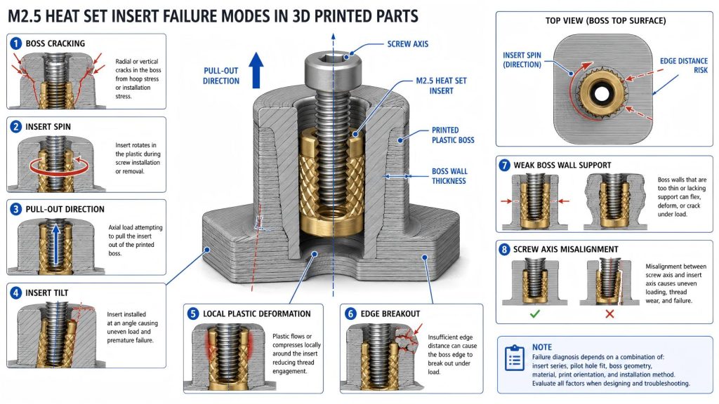
Engineering Overview
For the broader failure framework, see heat set insert failure modes.
An M2.5 heat set insert does not fail by itself. In most real printed parts, the failure occurs in the system around the insert: the pilot hole, the boss wall, the boss base, the surrounding material, the screw path, or the load direction.
Because M2.5 sits between M2 and M3, it has a mixed design character. It is more forgiving than M2 because it has more insert surface area and more boss volume. It is less forgiving than M3 because the available wall thickness, edge distance, and insert engagement area are still limited. This makes M2.5 failure diagnosis more useful when it is organized by engineering cause rather than by surface appearance only.
A cracked boss, spinning insert, loose screw, tilted insert, or pulled-out insert may look like separate problems, but they often share the same root causes: poor hole fit, insufficient boss support, weak material behavior, overheating, misalignment, or using M2.5 in a joint that should have been designed around M3.
Typical M2.5 Heat Set Insert Failure Modes
The table below provides engineering starting points for diagnosing M2.5 heat set insert failures. It does not represent guaranteed test results. Actual failure behavior depends on the insert series, printed material, print orientation, boss geometry, hole tolerance, installation method, and service load.
| Failure Mode | Common Cause | Visible Symptom | Engineering Diagnosis |
|---|---|---|---|
| Boss Cracking | Pilot hole too tight, boss wall too thin, excessive heat, or poor edge distance | Vertical crack, split boss, or crack toward nearest edge | The boss cannot absorb radial expansion or installation stress. |
| Insert Spin | Oversized pilot hole, weak knurl engagement, insufficient boss support, or over-tightening | Insert rotates when screw is tightened or removed | The plastic around the insert cannot resist rotational load. |
| Pull-Out | Shallow seating, poor insert engagement, weak boss base, or axial service load | Insert lifts out of boss with or without surrounding plastic damage | The insert does not have enough axial retention or load transfer into the part. |
| Insert Tilt | Off-axis installation, uneven heat, angled screw path, or weak pilot hole guidance | Insert sits at an angle or screw enters unevenly | The insert engagement is uneven, causing side load and local stress concentration. |
| Local Deformation | Excess heat, soft material behavior, high preload, or insufficient boss volume | Boss wall sinks, bulges, softens, or loses shape around insert | The plastic yields or creeps instead of holding a stable insert interface. |
| Edge Breakout | Boss placed too close to part edge, corner, thin wall, or cutout | Crack or tear propagates from boss toward nearby boundary | The surrounding part does not provide enough material support around the boss. |
| Torque Loss After Service | Repeated assembly, PETG creep, screw over-tightening, or gradual knurl wear | Joint feels loose after several screw cycles | The insert may still be seated, but the plastic has lost rotational grip or preload stability. |
Failure Mode 1: Boss Cracking
For installation-related diagnosis, review M2.5 installation failures.
If the boss is too small around the insert, review the boss OD ratio reference as a geometry check.
When cracking begins at the boss wall, compare the design against the minimum wall thickness reference.
Boss cracking is one of the most common M2.5 heat set insert failures. It usually happens when the pilot hole is too tight, the insert is installed too hot, the boss wall is too thin, or the boss is too close to an edge.
In PLA, boss cracking may happen during installation because the material is stiff but brittle. In PETG, cracking is less sudden but can still occur if the boss is undersized or overloaded. In ABS, cracking may combine with local softening if the insert is installed with too much heat or pressure.
For M2.5 inserts, boss cracking often indicates that the design used the screw size as the starting point instead of the insert outside diameter and required wall thickness.
Failure Mode 2: Insert Spin
Insert spin happens when the insert rotates inside the printed boss during screw tightening or screw removal. This is usually a torque resistance problem rather than a thread problem.
The most common causes are an oversized pilot hole, weak plastic flow into the knurls, shallow seating, insufficient boss wall thickness, or screw over-tightening. PETG can also lose rotational grip over time if the surrounding plastic relaxes under preload.
For M2.5 joints, insert spin is especially important because the screw is small enough for compact products but still large enough to generate damaging torque if tightened aggressively.
Failure Mode 3: Pull-Out
Pull-out occurs when the insert moves upward along the screw axis and separates from the printed boss. Sometimes the insert pulls out cleanly. In other cases, it tears plastic from the boss or breaks the boss base.
This failure is usually connected to poor seating depth, insufficient insert engagement length, weak boss base thickness, poor layer orientation, or high axial load. A boss can have acceptable torque resistance and still fail in pull-out if the load path below the insert is weak.
M2.5 inserts are better than M2 for pull-out resistance, but they still do not provide the same engagement margin as M3. High-tension joints should be checked carefully before choosing M2.5.
Failure Mode 4: Insert Tilt
Insert tilt happens when the insert is not seated along the correct axis. It can be caused by off-axis soldering iron pressure, uneven heat, a poorly guided pilot hole, or screw alignment errors between mating parts.
A tilted insert reduces both pull-out and torque performance because the knurls do not engage the plastic evenly. It can also cause the screw to pull sideways on the boss, creating local stress concentration and increasing the chance of cracking.
Small M2.5 bosses are less tolerant of tilt than larger bosses because there is less wall thickness available to absorb side load.
Failure Mode 5: Local Deformation
Local deformation occurs when the plastic around the insert softens, creeps, compresses, or bulges. It may not look as dramatic as a crack, but it can still reduce screw preload and long-term retention.
This failure is more likely when the insert is installed with excessive heat, the boss wall is too thin, the material softens under temperature, or the screw preload remains high over time. PETG and overheated ABS can show this pattern in compact M2.5 bosses.
Local deformation often appears as a joint that feels acceptable immediately after assembly but becomes loose later.
Failure Mode 6: Edge Breakout
Edge breakout happens when the boss fails toward a nearby edge, corner, cutout, slot, or thin wall. This is common when compact designs place M2.5 inserts too close to the boundary of the printed part.
The insert may be properly seated, and the pilot hole may be reasonable, but the surrounding part does not provide enough material to carry installation stress or screw load. The crack then follows the shortest weak path outward.
For M2.5 inserts, edge distance should be treated as part of the fastening design, not as leftover space after the enclosure shape is finished.
Failure Mode 7: Torque Loss After Repeated Assembly
Some M2.5 inserts do not fail immediately. Instead, they gradually lose torque feel after repeated screw tightening and removal. This is common in service covers, electronics housings, and small panels that are opened more than expected.
The cause may be plastic creep, worn knurl engagement, screw binding, over-tightening, or slight insert movement over time. PETG can be especially sensitive to long-term preload relaxation, while PLA may show sudden cracking if the joint is repeatedly stressed.
For repeated assembly, M2.5 should be chosen only when the boss has enough support and the screw torque can be controlled. If the joint will be opened frequently, M3 or a larger fastening structure may be more reliable.
Material-Specific Failure Patterns
PLA
PLA failure is often sharp and visible. The most common M2.5 failure patterns in PLA are boss cracking, edge breakout, and brittle fracture around the insert. PLA can provide good initial stiffness, but it does not tolerate excessive installation pressure or thin boss walls well.
PETG
PETG failure is often more gradual. It may tolerate installation without cracking, but it can relax under preload and lose torque resistance after repeated assembly. Common PETG failure patterns include insert spin, local deformation, and long-term torque loss.
ABS
ABS failure depends heavily on heat control and print quality. It can work well for functional parts, but overheating during installation may soften the boss too much and reduce knurl engagement. Common ABS failure modes include insert tilt, local deformation, and weakened boss support.
How to Reduce M2.5 Heat Set Insert Failures
- Start from insert OD, not thread size. Boss OD, wall thickness, and pilot hole fit should be based on the actual insert geometry.
- Use the correct pilot hole for the insert and material. Oversized holes increase spin and pull-out risk. Tight holes increase cracking risk.
- Design enough boss wall thickness. Compact bosses need enough surrounding material to resist radial expansion, torque, and pull-out forces.
- Maintain proper edge distance. Avoid placing M2.5 bosses too close to corners, cutouts, thin walls, or part boundaries.
- Control installation heat and pressure. Too much heat can deform the boss; too little heat can prevent proper plastic flow into the knurls.
- Seat the insert straight and fully. Insert tilt reduces engagement and creates uneven load paths.
- Match M2.5 to realistic service loads. Use M3 or a larger fastening structure when torque, vibration, or repeated service loads exceed the compact joint margin.
When M2.5 Failure Risk Is High
- The boss wall is thin because the enclosure is very compact.
- The insert is close to a corner, slot, or outside edge.
- The part will be opened and closed many times.
- The screw may be tightened by hand without torque control.
- The printed material is brittle, weakly bonded, or used near elevated temperature.
- The joint carries axial tension, vibration, or side load.
Related Engineering Guides
- M2.5 Heat Set Insert Dimensions Reference for 3D Printed Parts
- M2.5 Heat Set Insert Hole Size for 3D Printed Parts
- M2.5 Heat Set Insert Boss Design for 3D Printed Parts
- M2.5 Heat Set Insert Pull-Out Strength for 3D Printed Parts
- M2.5 Heat Set Insert Torque Resistance for 3D Printed Parts
- Torque Resistance of Heat Set Inserts in 3D Printed Parts
- Pull-Out Strength of Heat Set Inserts in 3D Printed Parts
- Heat Set Insert Edge Distance Reference for 3D Printed Parts
- PLA vs PETG vs ABS for Threaded Inserts
FAQ
What is the most common M2.5 heat set insert failure mode?
The most common failure modes are boss cracking, insert spin, and pull-out. The exact failure depends on pilot hole fit, boss wall thickness, material behavior, insert seating depth, and screw load.
Why does an M2.5 heat set insert spin in a printed boss?
An M2.5 insert usually spins when the pilot hole is oversized, the knurls do not engage enough plastic, the boss has insufficient wall support, or the screw is over-tightened during assembly or removal.
Why do M2.5 bosses crack during installation?
M2.5 bosses often crack when the pilot hole is too tight, the boss wall is too thin, the insert is installed too hot, or the boss is placed too close to an edge. PLA is especially sensitive to cracking.
Is M2.5 more reliable than M2 in 3D printed parts?
M2.5 is usually more forgiving than M2 because it has more insert surface area and boss volume. However, it still requires careful boss design and is not as forgiving as M3 for torque, pull-out, and repeated service loads.
When should I avoid M2.5 heat set inserts?
Avoid M2.5 when the boss must be very close to an edge, the part will carry high torque or tension, the joint will be opened frequently, or the design has enough room to use M3 with better structural margin.
Related Decision Resources
For insert selection, tool choice, and supplier comparison, use these decision-focused references after the engineering requirements are defined.