
Heat Set Inserts for 3D Printed Cable Strain Relief Brackets are used when printed parts need to hold cables, wire bundles, sensor leads, power wires, or harnesses without relying on plastic threads alone. In these assemblies, the insert does not only hold a screw. It helps maintain clamp force while the cable is pulled, bent, routed, serviced, or repeatedly handled.
Cable strain relief brackets create a different fastening problem from flat covers or simple mounting plates. The load often comes from cable movement, bending, vibration, accidental pulling, or repeated assembly of clamp halves. This means insert placement, boss support, screw preload, edge distance, and clamping surface design all matter.
Heat set inserts can make 3D printed cable brackets more serviceable and durable, but only if the printed structure around the insert is designed to resist clamp load and cable strain.
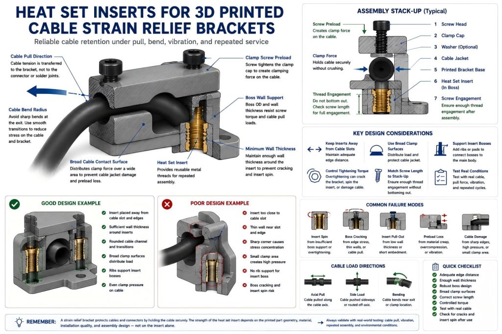
Why Cable Strain Relief Brackets Need Heat Set Inserts
Printed plastic threads can wear quickly when a cable clamp is opened, tightened, adjusted, or reassembled multiple times. Heat set inserts provide reusable metal threads that can better survive repeated screw cycles.
In a cable strain relief bracket, screws are often used to close a clamp around a cable or wire bundle. The screw load compresses the bracket, while the cable may apply bending or pulling force. If the insert loosens, spins, or pulls out, the clamp can lose grip and the cable strain may transfer to connectors, solder joints, or internal components.
Common Use Cases
3D printed cable strain relief brackets are common in prototypes, electronics fixtures, robotics systems, sensor housings, test equipment, and small-batch devices.
- sensor cable strain relief brackets
- robot wire harness clamps
- electronics enclosure cable exits
- USB, power, or signal cable retention blocks
- test fixture cable management brackets
- camera or sensor module cable clamps
- small machine wire routing clips
- prototype product cable support brackets
For related electronics and sensor applications, see Heat Set Inserts for Adjustable Camera and Sensor Mounts and Heat Set Inserts in Sensor Brackets.
How Cable Strain Loads Affect Insert Design
Cable strain relief brackets are not loaded only in screw tension. The cable may pull sideways, bend near the exit point, vibrate during motion, or apply repeated load to one side of the clamp. This creates combined stress around the insert bosses.
The insert may experience:
- screw tightening torque
- clamp preload from the cable bracket
- side load from cable pull direction
- vibration from moving equipment
- repeated screw removal during service
- local bending near thin clamp arms
- edge stress near cable slots or openings
This is why cable strain relief brackets should be designed as load paths, not just as printed blocks with threaded holes.
Insert Placement in Cable Brackets
Insert placement should support the clamp force without placing the insert too close to a cable slot, outer edge, or thin clamp arm. A common mistake is placing the insert directly beside a narrow slot where the remaining wall thickness is low.
Inserts should be placed where the surrounding boss can carry screw preload and resist cable pull. If the insert is too close to the cable opening, the boss may crack toward the slot or edge.
For edge support, see Heat Set Insert Edge Distance Reference for 3D Printed Parts and Heat Set Insert Minimum Wall Thickness Reference for 3D Printed Parts.
Boss Design Around Cable Clamp Screws
Cable clamps often use small bosses near slots, split lines, or thin walls. These bosses must resist both installation stress and tightening torque. If the boss wall is too thin, the insert may spin or split the plastic when the screw is tightened.
Good boss design for cable strain relief brackets should include:
- enough boss outside diameter around the insert
- sufficient wall thickness between the insert and cable slot
- rounded transitions near clamp arms
- ribs connecting the insert boss to the main bracket body
- enough material under the insert to resist pull-out
- print orientation that does not split along cable pull direction
For boss sizing, see Boss OD Ratio for Heat Set Inserts in 3D Printed Parts and How to Design Bosses for Heat Set Inserts.
Screw Preload and Cable Clamp Force
The screw in a cable strain relief bracket should create enough clamp force to hold the cable without crushing it or overstressing the printed part. Overtightening can crack the bracket, spin the insert, or deform the cable clamp surface.
For soft cable jackets, the clamp should distribute load over a broad contact surface. A narrow screw clamp can create local pressure that damages the cable or causes preload loss as the plastic and cable jacket relax over time.
For torque behavior, see Heat Set Insert Torque Range Reference for 3D Printed Parts.
Assembly Stack-Up in Cable Clamps
Cable strain relief brackets often have a clamp cap, screw head, optional washer, clearance hole, cable jacket, printed base, and heat set insert. All of these layers form the assembly stack-up.
If the screw is too short, it may not engage enough insert thread. If it is too long, it may bottom out before the clamp grips the cable. If the clamp cap is too flexible, the screw may feel tight while the cable is still not retained securely.
For stack-up planning, see Heat Set Insert Assembly Stack-Up Reference for 3D Printed Parts and Screw Engagement Length for Heat Set Inserts in 3D Printed Parts.
Clamp Geometry for Cable Strain Relief
The printed geometry should hold the cable without creating sharp stress points. A good strain relief bracket supports the cable over a length of contact, not only at a single screw location.
Useful geometry features include:
- rounded cable channels
- wide clamp surfaces
- relieved edges near cable exit points
- ribs behind insert bosses
- enough spacing between screw holes and cable slot
- smooth transitions between clamp body and mounting tabs
A cable should not be pinched by a sharp printed corner. The insert provides the screw thread, but the printed clamp surface determines how safely the cable load is distributed.
Material Considerations
Material choice affects both insert reliability and cable retention. A stiff material may hold shape well but crack near thin clamp arms. A tougher material may handle bending but lose preload over time.
| Material | Cable Bracket Behavior | Insert Design Note |
|---|---|---|
| PLA | Stiff but brittle under clamp and cable pull stress | Avoid thin clamp arms and keep torque conservative. |
| PETG | Tougher and more flexible, but prone to creep | Use broad clamp surfaces and test preload retention. |
| ABS | Better impact and temperature behavior | Check layer adhesion and boss support near cable slots. |
| ASA | Useful for exposed cable brackets | Maintain edge distance and avoid sharp cable exit stress. |
| Nylon | Good toughness and flexibility | Check long-term clamp force and screw preload relaxation. |
| Fiber-filled materials | Stiff and dimensionally stable | Avoid brittle cracking around bosses and clamp arms. |
For material comparison, see PLA vs PETG vs ABS for Threaded Inserts.
Common Failure Modes
Cable strain relief brackets often fail because the cable load is transferred into weak printed geometry near the insert or cable slot.
- insert spin during screw tightening
- boss cracking near the cable slot
- clamp arm splitting along layer lines
- insert pull-out under cable tension
- preload loss after cable jacket compression
- screw bottoming out before cable is clamped
- surface gap between clamp cap and printed base
- cable damage from sharp clamp geometry
For related failure paths, see Why Do Heat Set Inserts Fail Near Edges or Corners? and Why Does Screw Preload Drop in 3D Printed Insert Joints?.
Design Checklist
- Place inserts away from cable slots and thin edges.
- Keep enough wall thickness between the insert and cable opening.
- Use ribs or pads behind insert bosses.
- Use broad cable contact surfaces instead of sharp pressure points.
- Match screw length to the full clamp stack-up.
- Use controlled tightening torque to avoid crushing the cable or cracking the bracket.
- Check screw engagement after the clamp cap and washer are included.
- Test repeated cable pull and cable movement.
- Inspect for insert spin, boss cracking, and preload loss after use.
- Choose material based on cable load, temperature, flexibility, and service cycles.
Testing Cable Strain Relief Brackets
A cable strain relief bracket should be tested with the real cable, not only with the insert installed in an empty boss. The cable jacket, bend radius, clamp cap, and screw torque all affect performance.
A useful test should include:
- installing the insert using the final material and print orientation
- assembling the real cable or cable bundle
- tightening the clamp with the intended screw torque
- checking whether the cable moves under pull force
- checking whether the cable jacket is damaged
- cycling the cable through expected bending or handling
- removing and reinstalling the clamp cap several times
- checking for insert spin, boss cracks, and preload loss
FAQ
Are heat set inserts useful for 3D printed cable strain relief brackets?
Yes. Heat set inserts are useful when the cable bracket needs reusable screw threads, repeated service, or more reliable clamp fastening than printed plastic threads alone.
Where should inserts be placed in a cable strain relief bracket?
Inserts should be placed away from cable slots, thin clamp arms, and unsupported edges. The surrounding boss should have enough wall thickness and support to resist screw torque and cable pull.
Can overtightening damage a cable strain relief bracket?
Yes. Overtightening can crack the printed boss, spin the insert, deform the clamp, or damage the cable jacket. Use controlled torque and broad clamp contact surfaces.
What material is best for printed cable strain relief brackets?
The best material depends on load, temperature, flexibility, and service cycles. PETG, ABS, ASA, nylon, and filled materials may work well when geometry and insert support are designed properly.
Should cable strain relief brackets be tested with the real cable?
Yes. Cable jacket stiffness, diameter, bend direction, and pull force all affect bracket performance. Testing only the insert does not validate the strain relief design.
Related Guides
- Heat Set Insert Edge Distance Reference for 3D Printed Parts
- Heat Set Insert Minimum Wall Thickness Reference for 3D Printed Parts
- Boss OD Ratio for Heat Set Inserts in 3D Printed Parts
- Heat Set Insert Torque Range Reference for 3D Printed Parts
- Heat Set Insert Assembly Stack-Up Reference for 3D Printed Parts
- Screw Engagement Length for Heat Set Inserts in 3D Printed Parts
- Why Do Heat Set Inserts Fail Near Edges or Corners?
- Why Does Screw Preload Drop in 3D Printed Insert Joints?