
M2 heat set insert dimensions are important when designing small 3D printed parts that need reusable metal threads. Because M2 screws are small, the plastic structure around the insert has limited material available to resist pull-out, rotation, cracking, preload loss, and long-term loosening.
This reference explains the main M2 heat set insert dimensions that matter in 3D printed parts, including insert length, outside diameter, printed hole size, boss diameter, boss depth, wall thickness, and screw engagement length.
M2 heat set insert dimensions are not universal. Different manufacturers use different body diameters, knurl patterns, pilot geometries, lengths, and recommended hole sizes. Always confirm the actual insert datasheet before finalizing the printed hole.
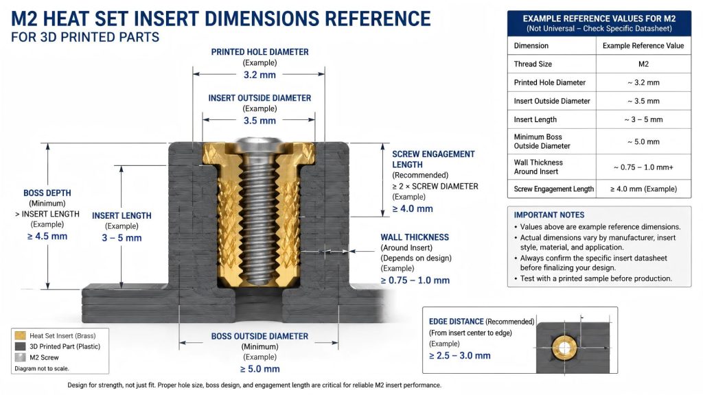
Typical M2 Heat Set Insert Dimensions
A typical M2 heat set insert used in 3D printed parts is a small brass threaded insert with an internal M2 thread and an external knurled body. During installation, heat softens the surrounding thermoplastic and allows plastic to flow around the insert body.
As a practical reference, some M2 heat set insert specifications list values around a 3.2 mm hole diameter, 3.5 mm insert outside diameter, 3–5 mm insert length, and about 5.0 mm minimum boss outside diameter. These values should be treated as example reference dimensions, not a universal standard for every M2 insert.
| Dimension | Example Reference Value | Why It Matters |
|---|---|---|
| Thread size | M2 | Defines the screw size used in the assembly. |
| Printed hole diameter | Example: around 3.2 mm | Affects insertion fit, plastic flow, torque resistance, and boss stress. |
| Insert outside diameter | Example: around 3.5 mm | Determines the minimum surrounding boss structure needed for support. |
| Insert length | Example: around 3–5 mm | Affects boss depth, screw engagement, and pull-out resistance. |
| Minimum boss outside diameter | Example: around 5.0 mm | Helps prevent cracking, edge breakout, and weak insert support. |
| Wall thickness around insert | Depends on insert OD and boss design | Controls cracking risk and load distribution around the insert. |
For broader hole sizing principles, see the Heat Set Insert Hole Size Guide.
Why M2 Inserts Need More Care Than Larger Inserts
M2 inserts are less forgiving than M3, M4, or M5 inserts because the printed structure around the insert is much smaller. A small error in hole size, boss wall thickness, insert depth, or screw length can become significant at this scale.
Common M2 insert problems include:
- the printed hole being too large
- the printed hole being too small
- the insert spinning during screw tightening
- the boss cracking during installation
- the insert sitting proud of the surface
- the screw bottoming out below the insert
- plastic flowing into the internal thread
- the insert weakening after repeated assembly
- the insert being placed too close to an edge
In larger insert joints, the surrounding plastic volume may absorb small design errors. In M2 insert joints, there is much less structural margin.
For a larger reference comparison, see the M3 Heat Set Insert Dimensions Reference.
M2 Heat Set Insert Hole Size Considerations
For the next sizing step, see M2 heat set insert hole size.
The printed hole for an M2 heat set insert should not be chosen from the M2 screw size alone. The hole must match the actual insert body geometry, especially the outside diameter, knurl diameter, pilot diameter, and insert length.
A good M2 insert hole should:
- guide the insert straight during installation
- leave enough plastic for the knurls to displace and grip
- avoid excessive clearance that reduces torque resistance
- avoid excessive interference that cracks the boss
- provide enough depth for the full insert length
- reduce the chance of plastic flowing into the internal thread
The hole is usually smaller than the largest knurled diameter of the insert, but the exact size depends on the insert style, printed material, printer accuracy, and installation process.
For failure cases caused by incorrect hole size, see Why Do Heat Set Inserts Fail When the Hole Is Too Large? and Why Do Heat Set Inserts Fail When the Hole Is Too Small?.
Boss Diameter and Wall Thickness for M2 Inserts
For structural support limits, check the minimum wall thickness reference.
For boss sizing geometry, compare this value with the boss OD ratio reference.
The boss around an M2 heat set insert must provide enough plastic to support the insert during installation and use. If the boss wall is too thin, the insert may split the boss, deform the surrounding plastic, or lose torque resistance during screw tightening.
For M2 inserts, the boss should be designed around the insert outside diameter, not only around the M2 screw thread. The outer knurled diameter is the critical geometry because it defines how much plastic is displaced during heat insertion.
When designing an M2 insert boss, check:
- largest insert outside diameter
- recommended printed hole diameter
- remaining wall thickness around the insert
- distance from the insert to nearby edges
- layer orientation of the printed part
- expected screw torque
- whether the screw will be removed repeatedly
For general boss design principles, see How to Design Bosses for Heat Set Inserts.
Insert Length and Boss Depth
The boss depth should be greater than the insert length. If the boss is too shallow, the insert may bottom out, sit proud of the surface, or push molten plastic into the thread.
For M2 inserts, depth control matters because the insert is short. A small amount of depth error can affect the final seating position and screw engagement.
A practical boss depth check should include:
- the insert must fit fully inside the boss
- there should be enough material below the insert to support the load
- the screw should not bottom out below the insert
- the installation tool should not push the insert too deep
- displaced plastic should not block the internal thread
If the insert must sit flush with the surface, the printed hole depth and installation control become more important.
Screw Engagement Length for M2 Inserts
M2 screws are small, so screw engagement length must be checked carefully. The screw should engage enough thread inside the insert to carry the intended load, but it should not bottom out.
Too little engagement may cause weak clamping or thread damage. Too much screw length may push against the bottom of the hole, lift the insert, or create false tightening resistance.
When selecting screw length, check:
- insert internal thread depth
- part thickness
- mating component thickness
- washer thickness, if used
- required clamp force
- clearance below the insert
For a deeper engineering explanation, see Screw Engagement Length for Heat Set Inserts in 3D Printed Parts.
Material Behavior: PLA, PETG, ABS, and Nylon
M2 heat set insert performance depends strongly on the printed material.
PLA is stiff, but it can crack if the hole is too tight, the boss is too thin, or the insert is overheated. PETG is tougher, but it can lose preload over time because of creep. ABS can tolerate installation heat better than PLA, but it still depends on hole fit and boss geometry. Nylon and carbon fiber nylon may offer better toughness, but printed hole tolerance, moisture behavior, and fiber-filled material behavior still need to be checked.
The same M2 insert may need different hole tuning in different materials. A hole that works in PETG may not work the same way in PLA, ABS, or nylon.
For material comparison, see PLA vs PETG vs ABS for Threaded Inserts.
Pull-Out and Torque Resistance in Small M2 Insert Joints
M2 heat set inserts are often used in compact parts such as electronics housings, sensor mounts, lightweight brackets, small robots, and printed mechanisms. These parts may not have much plastic around the insert.
Pull-out strength and torque resistance depend on more than the insert itself. They are affected by:
- printed hole size
- insert length
- knurl geometry
- boss diameter
- boss depth
- edge distance
- material stiffness and creep behavior
- layer orientation
- installation temperature
- screw tightening torque
For related engineering principles, see Pull-Out Strength of Heat Set Inserts in 3D Printed Parts and Torque Resistance of Heat Set Inserts in 3D Printed Parts.
Recommended Design Checks Before Printing
Before finalizing an M2 heat set insert design, check these items:
- Confirm the actual manufacturer dimensions of the insert.
- Measure the largest outside diameter of the insert body.
- Confirm the recommended hole size from the supplier.
- Add enough boss wall thickness around the insert.
- Add enough boss depth for the full insert length.
- Confirm screw length and thread engagement.
- Check edge distance and nearby thin walls.
- Print a small test coupon before committing to the final part.
- Test insertion temperature and insertion force.
- Test screw tightening torque after cooling.
For small insert sizes like M2, a test coupon is often more reliable than assuming the CAD hole will print exactly as designed.
Common M2 Heat Set Insert Design Mistakes
Hole Too Large
If the printed hole is too large, the melted plastic may not fully flow into the knurl pattern. This can reduce torque resistance and allow the insert to spin.
See also: Why Do Heat Set Inserts Spin in 3D Printed Parts?
Hole Too Small
If the hole is too small, the insert may force too much plastic outward during installation. This can crack the boss, deform the wall, or push plastic into the thread.
See also: Why Do Bosses Crack Around Heat Set Inserts?
Boss Too Thin
If the boss is too thin around the insert, the structure may crack during insertion or fail during screw tightening. M2 bosses are especially sensitive because the available wall thickness is small.
Insert Too Close to an Edge
M2 inserts are often placed in compact parts. If the insert is too close to the edge, the load path becomes weak and the insert may pull out, split the wall, or deform the corner.
See also: Why Do Heat Set Inserts Fail Near Edges or Corners?
Screw Too Long
A screw that is too long may bottom out inside the insert or below the insert. This can push the insert upward or create false tightening torque.
No Test Coupon
Because M2 inserts are small, print tolerance matters. A test coupon can reveal whether the hole prints too tight, too loose, oval, rough, or inconsistent across materials.
Practical Reference Summary
M2 heat set insert dimensions should be treated as insert-specific engineering data, not as a universal value. The most important dimensions are insert length, outside diameter, knurl diameter, printed hole size, boss wall thickness, boss depth, and screw engagement length.
For small 3D printed assemblies, the insert should be designed as part of a complete fastening structure. The insert, boss, screw, printed material, layer orientation, hole tolerance, and assembly load all affect reliability.
A good M2 insert design is not just a small hole with a metal thread inside it. It is a compact load-bearing structure that must survive heat installation, screw tightening, repeated use, and long-term material behavior.
FAQ
What is the typical hole size for an M2 heat set insert?
Some M2 heat set insert references list a hole size around 3.2 mm, but this is not universal. The correct hole size depends on the insert manufacturer, insert geometry, printed material, and printer tolerance.
What is the typical outside diameter of an M2 heat set insert?
Some M2 heat set inserts have an outside diameter around 3.5 mm, but different insert styles may vary. Always check the actual datasheet and measure the insert before finalizing the CAD hole.
Can I use the same hole size for all M2 heat set inserts?
No. M2 heat set inserts can have different outside diameters, knurl profiles, pilot shapes, and lengths. The printed hole should match the actual insert geometry and supplier recommendation.
Why do M2 heat set inserts spin in 3D printed parts?
M2 inserts can spin if the hole is too large, the plastic does not flow into the knurl pattern, the boss is too weak, or the screw torque exceeds the joint’s torque resistance.
How deep should the boss be for an M2 heat set insert?
The boss should be deep enough to fully contain the insert, allow proper installation, and prevent screw bottoming. The required boss depth depends on insert length, screw length, and part geometry.
Should I print a test coupon for M2 heat set inserts?
Yes. M2 inserts are small and sensitive to print tolerance. A test coupon helps verify hole size, insertion depth, installation temperature, and screw tightening behavior before using the design in a final part.
Source Notes
Example M2 reference values vary by supplier and insert style. Always confirm the specific datasheet for the insert being used before finalizing a production design.
Related Decision Resources
For insert selection, tool choice, and supplier comparison, use these decision-focused references after the engineering requirements are defined.