
M4 heat set insert failure modes usually come from a mismatch between insert size, pilot hole fit, boss geometry, installation heat, printed material behavior, screw tightening load, and the way service forces travel through the 3D printed part.
M4 inserts are commonly used in functional printed brackets, covers, fixtures, tool mounts, equipment housings, and medium-load assemblies. They provide more fastening capacity than M3 while requiring less boss volume and installation heat than M5. This makes M4 a practical middle-size insert, but it still needs careful design and installation.
This article explains the most common M4 heat set insert failure modes in 3D printed parts, including boss cracking, insert spin, pull-out, insert tilt, local deformation, edge breakout, weak seating, and installation heat damage.
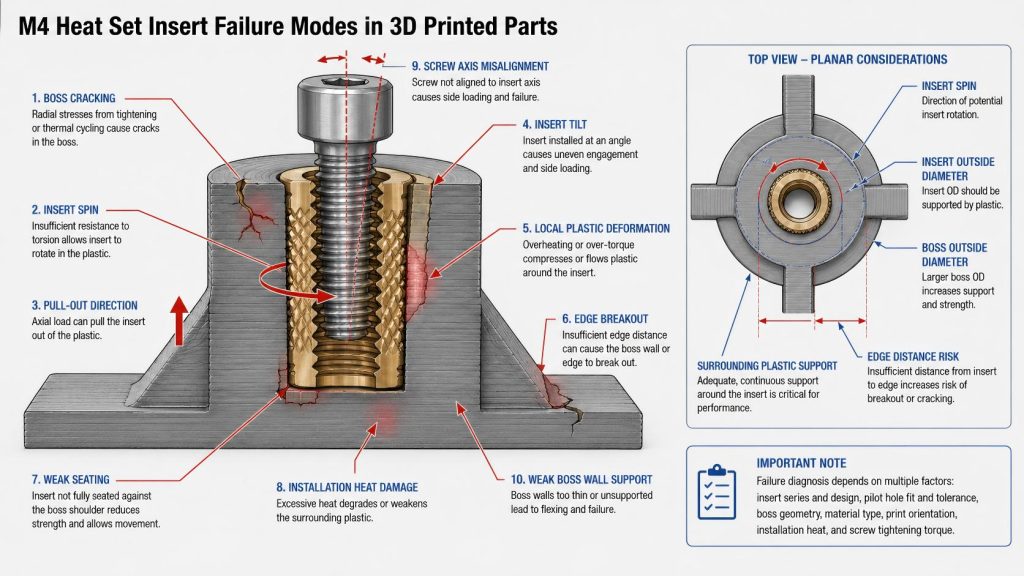
Engineering Overview
For the broader failure framework, see why heat set inserts fail.
An M4 heat set insert usually fails as part of a printed fastening system, not as an isolated brass component. The surrounding pilot hole, boss wall, boss base, printed material, layer orientation, screw path, and edge distance all influence whether the insert remains stable after installation and service loading.
M4 sits between M3 and M5 in practical design behavior. It is stronger and more forgiving than M3 in many functional assemblies, but it can still damage a compact boss if the hole is too tight, the wall is too thin, the insert is overheated, or the screw is over-tightened. Compared with M5, M4 is easier to package into printed parts, but it still needs enough boss support to resist torque and pull-out loads.
For M4 failure diagnosis, the key question is not only “what broke?” but “which engineering variable lost control?” A cracked boss, spinning insert, tilted insert, or pulled-out boss often points back to pilot hole tolerance, boss wall thickness, seating depth, material behavior, or installation alignment.
Typical M4 Heat Set Insert Failure Modes
The table below provides engineering starting points for diagnosing M4 insert failures. These are not universal test results. Actual failure behavior depends on insert series, knurl design, printed material, boss geometry, pilot hole tolerance, print orientation, installation heat, and service loading.
| Failure Mode | Common Cause | Visible Symptom | Engineering Diagnosis |
|---|---|---|---|
| Boss Cracking | Tight pilot hole, thin boss wall, brittle material, excessive insertion force, or poor edge distance | Vertical crack, split boss, or crack toward nearby edge | The boss cannot absorb installation expansion or screw loading stress. |
| Insert Spin | Oversized pilot hole, weak knurl engagement, insufficient wall support, or excessive screw torque | Insert rotates when screw is tightened or removed | The plastic around the insert cannot resist rotational load. |
| Pull-Out | Shallow seating, weak insert engagement, poor boss base support, or axial service load | Insert lifts out of the boss with or without surrounding plastic | The insert does not have enough axial retention or load transfer into the part. |
| Insert Tilt | Off-axis installation, uneven heat, poor pilot hole guidance, or angled screw path | Insert sits at an angle or screw enters unevenly | Uneven engagement creates side load, torque imbalance, and reduced joint reliability. |
| Local Plastic Deformation | Excess heat, PETG creep, high preload, soft material behavior, or compact boss geometry | Boss bulges, sinks, softens, or loses shape around the insert | The plastic yields or creeps instead of maintaining stable insert engagement. |
| Edge Breakout | Boss placed too close to part edge, corner, cutout, slot, or thin wall | Crack travels from the boss toward a nearby boundary | The surrounding part does not provide enough material support around the insert. |
| Weak Seating | Insufficient heat, shallow installation, poor hole depth, or stopping before full seating | Insert sits proud, wobbles, or does not support screw engagement properly | The insert did not reach a stable engagement depth. |
| Installation Heat Damage | Excessive heat dwell, overheated tool, slow insertion, or heat-sensitive material | Softened boss, smeared plastic, sunken insert, or reduced knurl definition | The installation process damaged the plastic before the joint entered service. |
Failure Mode 1: Boss Cracking
Boss cracking is one of the most visible M4 heat set insert failures. It usually happens when the pilot hole is too tight, the boss wall is too thin, the insert is forced into the plastic, or the boss is too close to an edge.
PLA is especially sensitive to cracking because it is stiff but brittle. PETG may deform before cracking, while ABS may soften if too much heat is applied. In M4 designs, cracking often starts where the wall is thinnest or where the boss connects to a nearby feature.
If an M4 boss cracks during installation, the cause is often a combined problem: hole fit, wall thickness, insertion pressure, and material brittleness all working against the boss at once.
Failure Mode 2: Insert Spin
For the size-specific insert spin mechanism, see M4 insert spin and torque failure.
Insert spin happens when the insert rotates inside the boss during screw tightening or removal. This is a torque resistance failure. The screw thread may still be intact, but the insert is no longer locked to the printed plastic.
Common causes include an oversized pilot hole, weak plastic flow into the insert knurls, shallow seating, insufficient boss wall thickness, or over-tightening. PETG can also lose rotational grip over time if the plastic relaxes under preload.
For M4 inserts, insert spin is especially important in service panels, brackets, and parts that are opened repeatedly. A joint may survive the first assembly but fail later when the screw is removed.
Failure Mode 3: Pull-Out
Pull-out occurs when the insert moves upward along the screw axis and separates from the printed boss. Sometimes the insert pulls out cleanly. In other cases, it carries part of the boss wall or boss base with it.
This failure can be caused by shallow seating depth, insufficient insert engagement length, poor layer orientation, weak boss base support, or axial service loads. A well-seated M4 insert can still pull out if the surrounding printed structure is too weak to transfer load.
Pull-out should be evaluated together with boss base thickness and screw engagement length, not just the insert size.
Failure Mode 4: Insert Tilt
Insert tilt happens when the insert is not seated along the correct screw axis. It can be caused by an angled soldering iron, poor pilot hole guidance, uneven heat, or pushing the insert before the plastic softens evenly.
A tilted insert reduces both torque resistance and pull-out strength because the knurls do not engage evenly. It can also cause the screw to enter at an angle, creating side load and uneven stress in the boss.
M4 is more tolerant than smaller inserts, but alignment still matters in assemblies where the screw passes through a mating part or where repeated service is expected.
Failure Mode 5: Local Plastic Deformation
Local deformation occurs when the plastic around the insert yields, creeps, bulges, compresses, or softens. This failure may not appear immediately. The insert may look well seated, but the joint can lose torque feel or preload stability after use.
PETG is more likely to show gradual deformation under sustained preload. ABS can deform if overheated during installation. PLA may crack instead of deforming, but local stress whitening or small crushed zones can still appear.
For M4 joints, local deformation often means the boss geometry, material, or screw preload is not matched to the service condition.
Failure Mode 6: Edge Breakout
Edge breakout occurs when the boss cracks or tears toward a nearby edge, corner, cutout, slot, or thin wall. This is common when an M4 insert is placed into a compact feature without enough surrounding material.
M4 requires more edge distance than small inserts because installation expansion and screw load are larger. If the boss is close to a boundary, the failure path may travel outward instead of staying inside the boss.
Edge distance should be checked during part design, not after the enclosure shape is already fixed.
Failure Mode 7: Weak Seating
Weak seating occurs when the insert does not reach the intended depth or does not develop proper knurl engagement. The insert may sit proud, wobble slightly, interfere with the mating part, or provide poor screw engagement.
This can happen when the installation temperature is too low, the insert is not heated long enough, the pilot hole is too tight, the hole depth is insufficient, or the user stops before the insert reaches the correct seating depth.
Weak seating often leads to later insert spin, pull-out, or screw misalignment.
Failure Mode 8: Installation Heat Damage
Installation heat damage happens when too much heat is transferred into the boss. The insert may sink too deeply, the boss top may soften, or the plastic around the knurls may smear instead of forming a stable mechanical lock.
M4 inserts require more heat than M3, so heat control becomes more important. The goal is controlled plastic flow around the insert knurls, not full softening of the entire boss.
Heat damage may not always look severe, but it can reduce long-term torque resistance and pull-out strength.
Material-Specific Failure Patterns
PLA
PLA often fails by cracking, splitting, or stress whitening. For M4 inserts, the main PLA risks are tight pilot holes, thin boss walls, excessive insertion force, and poor edge distance. PLA can provide good initial stiffness, but it has limited tolerance for installation stress.
PETG
PETG often fails more gradually. It may tolerate M4 installation without cracking, but it can deform or creep under screw preload. Common PETG failure patterns include insert spin after service, local boss deformation, and loss of torque resistance after repeated assembly.
ABS
ABS failure depends heavily on heat control and print quality. ABS may work well for M4 functional parts, but overheating can soften the boss and weaken knurl engagement. Common ABS failure modes include insert tilt, local deformation, weak seating, and heat-damaged boss structure.
How to Reduce M4 Heat Set Insert Failures
- Start from insert OD, not thread size alone. Boss design should be based on the actual insert outside diameter, knurl geometry, and required surrounding wall thickness.
- Use the correct pilot hole for the insert and material. Oversized holes increase spin and pull-out risk. Tight holes increase cracking and deformation risk.
- Provide enough boss wall thickness. M4 bosses need enough surrounding plastic to resist installation expansion, screw torque, and pull-out loads.
- Maintain proper edge distance. Avoid placing M4 inserts too close to corners, cutouts, slots, or thin walls.
- Control installation heat and pressure. Let the insert sink under heat instead of forcing it into cold plastic.
- Seat the insert straight and fully. Tilted or shallow inserts reduce torque resistance and pull-out strength.
- Allow the plastic to cool before loading. Tightening screws too soon can move the insert or weaken knurl engagement.
- Match M4 to realistic service loads. If the joint carries high torque, vibration, or repeated service loads, check whether M5 or a redesigned boss structure is needed.
When M4 Failure Risk Is High
- The boss wall is thin relative to the insert outside diameter.
- The insert is close to an edge, corner, slot, or cutout.
- The pilot hole varies because of print shrinkage or poor calibration.
- The insert is installed by hand without vertical guidance.
- The screw is tightened strongly after installation.
- The material is brittle, heat-sensitive, or prone to creep.
- The boss base is shallow or poorly connected to the main printed body.
- The part is expected to handle repeated assembly or vibration.
Related Engineering Guides
- M4 Heat Set Insert Dimensions Reference for 3D Printed Parts
- M4 Heat Set Insert Hole Size for 3D Printed Parts
- M4 Heat Set Insert Boss Design for 3D Printed Parts
- M4 Heat Set Insert Pull-Out Strength for 3D Printed Parts
- M4 Heat Set Insert Installation Guide for 3D Printed Parts
- Torque Resistance of Heat Set Inserts in 3D Printed Parts
- Pull-Out Strength of Heat Set Inserts in 3D Printed Parts
- Heat Set Insert Installation Temperature for 3D Printed Parts
- Heat Set Insert Edge Distance Reference for 3D Printed Parts
- PLA vs PETG vs ABS for Threaded Inserts
FAQ
What is the most common M4 heat set insert failure mode?
The most common M4 failure modes are boss cracking, insert spin, pull-out, insert tilt, and local deformation. The exact failure depends on pilot hole fit, boss geometry, installation heat, material behavior, and screw load.
Why does an M4 heat set insert spin in a 3D printed part?
An M4 insert usually spins when the pilot hole is oversized, the knurls do not engage enough plastic, the boss wall is too thin, or the screw is tightened beyond what the printed boss can resist.
Why do M4 bosses crack during installation?
M4 bosses often crack when the pilot hole is too tight, the boss wall is too thin, the material is brittle, the insert is forced downward, or the boss is placed too close to an edge or corner.
Is M4 more reliable than M3 in 3D printed parts?
M4 can be more reliable than M3 when the printed part has enough boss volume, wall thickness, and edge distance. If the boss is too compact, M4 may create more installation stress than the printed structure can support.
When should I avoid M4 heat set inserts?
Avoid M4 inserts when the boss cannot provide enough wall thickness, base support, or edge distance. If the geometry is too small, M3 may be safer. If the load is too high, M5 or a redesigned fastening structure may be needed.
Related Decision Resources
For insert selection, tool choice, and supplier comparison, use these decision-focused references after the engineering requirements are defined.