
M3 heat set insert failure modes usually come from a mismatch between insert geometry, pilot hole size, boss design, installation quality, material behavior, and the actual load applied during assembly or service.
M3 is one of the most common heat set insert sizes used in 3D printed parts. It is small enough for compact assemblies but strong enough for many functional brackets, electronics housings, fixtures, covers, and serviceable components. Because M3 is used so widely, it is also one of the most common sizes where insert failures appear: insert spin, pull-out, boss cracking, tilted seating, weak screw engagement, and loss of holding strength after repeated assembly.
This guide explains the most common M3 heat set insert failure modes in 3D printed parts and how to diagnose them based on hole size, boss geometry, installation process, material choice, screw tightening, and repeated use.
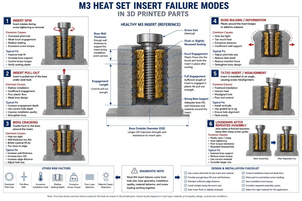
Engineering Overview
An M3 heat set insert works only when the insert and the printed boss act as one mechanical system. The brass insert provides the internal thread, but the surrounding plastic provides the structure that resists pull-out, rotation, cracking, and screw preload.
Failure can occur at several points in that system. A poor M3 heat set insert hole size can reduce knurl engagement. Weak M3 boss design can allow cracking or deformation. Poor M3 heat set insert installation can tilt, overheat, or under-seat the insert. If the joint sees repeated assembly or high screw torque, poor M3 torque resistance can cause the insert to spin.
For M3 inserts, failure is often not caused by one single mistake. More often, several small issues combine: a slightly loose hole, a thin boss wall, a warm PETG part, a screw tightened too hard, or an insert installed at a slight angle.
Common M3 Heat Set Insert Failure Modes
| Failure Mode | What It Looks Like | Common Causes | Typical Fix |
|---|---|---|---|
| Insert Spin | The insert rotates when the screw is tightened or removed | Oversized hole, weak knurl engagement, shallow seating, excessive screw torque | Improve hole fit, seating depth, boss support, and torque control |
| Insert Pull-Out | The insert pulls out of the boss under axial load | Shallow installation, short engagement, weak plastic flow, poor boss design | Increase engagement depth, improve installation, verify boss strength |
| Boss Cracking | The boss splits, shows stress whitening, or cracks near the insert | Hole too tight, wall too thin, brittle material, insert too close to edge | Increase boss OD, wall thickness, edge distance, and reduce installation force |
| Boss Bulging | Plastic around the insert swells or deforms outward | Hole too tight, too much heat, insufficient boss wall support | Adjust pilot hole, reduce heat dwell, strengthen boss geometry |
| Tilted Insert | The screw enters at an angle or binds during assembly | Freehand installation, uneven heat, misaligned hole, poor tool control | Use vertical installation axis, guided tip, or installation jig |
| Weak Thread Engagement | Screw does not hold enough load or bottoms out too early | Insert seated too deep, wrong screw length, insufficient engagement length | Check insert depth, screw length, and assembly stack-up |
| Plastic Softening Around Insert | Insert feels loose after heating or use in warm conditions | Overheating, weak material choice, PETG relaxation, poor cooling | Control installation heat and use material-specific design rules |
| Failure After Repeated Assembly | Joint works at first but loosens after many screw cycles | Plastic wear, creep, over-tightening, poor torque resistance | Improve boss support, reduce screw torque, and consider larger insert size |
Failure Mode 1: Insert Spin
Insert spin is one of the most common M3 heat set insert failures. It happens when the insert rotates inside the printed boss instead of staying locked in place while the screw is tightened or removed.
The most common causes are an oversized pilot hole, weak knurl engagement, shallow seating, or excessive screw tightening torque. If the insert spins during first tightening, the anti-rotation interface was probably weak from the beginning. If it spins during screw removal, the screw may have bound, the material may have relaxed, or the insert may have lost grip after repeated use.
Insert spin is closely related to pilot hole fit and torque resistance. If this failure appears often, review both the pilot hole tolerance and the size-specific M3 torque resistance design.
Failure Mode 2: Insert Pull-Out
Insert pull-out occurs when the insert is pulled upward or out of the boss under axial screw load. This can happen during assembly, service loading, disassembly, or when the mating part applies tension to the screw.
For M3 inserts, pull-out failure often points to shallow seating, poor plastic flow into the knurls, insufficient hole depth, weak material around the insert, or a boss that does not have enough structure to transfer load into the part.
If pull-out is the main problem, compare the design against the M3 heat set insert pull-out strength reference. Pull-out strength depends on engagement length, material behavior, print orientation, and how well the insert was installed.
Failure Mode 3: Boss Cracking
Boss cracking happens when the printed boss cannot absorb the installation or service stress around the insert. In PLA, this may appear as a sudden crack or stress whitening. In PETG or ABS, it may appear as deformation, splitting, or a crack along layer lines.
Common causes include a pilot hole that is too tight, insufficient wall thickness, small boss outside diameter, poor edge distance, brittle material, or excessive insertion force. Boss cracking can also happen if the insert is installed too close to a corner, slot, cutout, or unsupported edge.
Boss cracking should not be treated only as an installation problem. It usually means the printed structure is not giving the insert enough support. Check the boss OD ratio and minimum wall thickness before changing only the installation temperature.
Failure Mode 4: Boss Bulging or Local Deformation
Boss bulging occurs when plastic around the insert is pushed outward or softened too much during installation. It is often caused by a tight pilot hole, excessive installation heat, excessive pressing force, or not enough surrounding wall support.
Bulging can reduce dimensional accuracy and may interfere with mating parts. It can also weaken the insert interface because the plastic is displaced outward instead of forming a controlled lock around the knurls.
In PETG and ABS, local deformation may not show as a crack. The boss may simply become swollen, soft, or slightly distorted. In precision assemblies, even small deformation around an M3 insert can affect alignment.
Failure Mode 5: Tilted Insert
A tilted insert is installed at an angle instead of along the intended screw axis. This can cause screw binding, poor mating alignment, uneven load transfer, reduced pull-out strength, and reduced torque resistance.
Tilted installation is common when inserts are installed freehand with a soldering iron. It can also happen when the pilot hole is not perpendicular, the insert starts at an angle, the iron tip is not centered, or one side of the boss softens faster than the other.
A tilted M3 insert may look acceptable from above but cause problems during assembly. If the screw does not enter smoothly, or if the mating part does not sit flat, check insert alignment before assuming the screw or thread is defective.
Failure Mode 6: Weak Screw Engagement
Weak screw engagement happens when the screw does not engage enough of the insert thread or when the screw bottoms out before clamping the assembly properly. This is not always an insert retention problem, but it can make the assembly feel weak.
Common causes include incorrect screw length, insert seated too deep, shallow hole depth, stack-up mismatch, or using a screw that does not match the assembly thickness.
For serviceable M3 assemblies, screw engagement should be checked together with seating depth and stack-up. The insert may be installed correctly, but the screw may still be too short or too long for the final assembly.
Failure Mode 7: Plastic Softening Around the Insert
Plastic softening around an M3 insert can happen during installation or during service. During installation, excessive heat dwell can melt too much plastic around the insert. During service, warm environments or sustained screw preload can allow some materials to relax.
PETG is especially sensitive to long-term relaxation under preload. ABS may tolerate heat better than PLA, but it can still lose local definition if overheated during installation. PLA can hold a crisp shape at first, but it may crack if overstressed.
If the insert feels stable immediately after installation but becomes loose later, the issue may be material relaxation, creep, heat exposure, or repeated screw cycling rather than simple installation error.
Failure Mode 8: Failure After Repeated Assembly
M3 inserts are often used in parts that are opened and closed many times. A joint may work well during the first assembly but gradually loosen after repeated screw cycles.
Repeated assembly can wear the plastic around the knurls, reduce preload stability, create screw binding, or slowly rotate the insert if torque resistance is marginal. Over-tightening during each cycle accelerates this failure.
For repeated assembly, M3 can work well when the boss is properly sized and screw torque is controlled. If the joint is opened frequently or carries higher load, a larger insert size, stronger boss, or different assembly strategy may be needed.
Material-Specific Failure Patterns
PLA
PLA often provides good initial stiffness and a crisp mechanical lock around the insert. However, it is also more brittle than PETG and ABS. M3 insert failures in PLA often appear as cracking, stress whitening, edge breakout, or sudden boss splitting.
PLA failures are commonly caused by tight pilot holes, thin boss walls, excessive insertion force, insert placement too close to an edge, or screw over-tightening after installation.
PETG
PETG is tougher and more forgiving during installation, so it may crack less often than PLA. However, PETG can relax under sustained screw preload and repeated use. M3 insert failures in PETG often appear as gradual loosening, insert spin after repeated assembly, or boss deformation instead of sudden cracking.
PETG designs usually need conservative boss support, controlled screw torque, and enough cooling time after installation.
ABS
ABS can be reliable for functional M3 insert assemblies, especially when impact resistance or heat tolerance matters. However, ABS still requires controlled installation heat and good print quality.
M3 insert failures in ABS often come from overheating, poor layer adhesion, tilted installation, or insufficient boss support. If the boss softens too much during installation, the insert may not form a strong mechanical lock after cooling.
How to Diagnose an M3 Insert Failure
When an M3 heat set insert fails, start by identifying what failed first. Did the insert rotate? Did it pull out? Did the boss crack? Did the screw bind? Did the joint loosen after repeated use?
| Observed Problem | Likely Cause | First Area to Check |
|---|---|---|
| Insert spins during tightening | Oversized hole, weak knurl engagement, excessive screw torque | Pilot hole fit and torque resistance |
| Insert pulls out | Shallow seating, weak plastic flow, insufficient engagement length | Installation depth and pull-out strength |
| Boss cracks during installation | Hole too tight, wall too thin, brittle material | Hole size and boss wall thickness |
| Boss bulges or melts | Too much heat, tight hole, excessive pressure | Installation heat and hole fit |
| Screw binds or enters crooked | Tilted insert or misaligned hole | Installation alignment |
| Joint loosens after repeated use | Plastic creep, wear, over-tightening, poor torque resistance | Material behavior and repeated assembly loading |
Prevention Checklist
- Choose the M3 insert based on actual insert OD, length, and knurl geometry.
- Use a pilot hole that matches the insert series and printed material.
- Provide enough boss outside diameter and wall thickness.
- Avoid placing M3 inserts too close to unsupported edges, slots, or cutouts.
- Control installation heat and avoid excessive heat dwell.
- Install the insert straight along the screw axis.
- Seat the insert flush or slightly recessed where appropriate.
- Let the insert cool before applying screw preload.
- Use controlled screw tightening torque.
- Consider material creep, brittleness, and layer adhesion before finalizing the design.
When M3 Is the Right Size
M3 is usually a strong choice for general-purpose 3D printed assemblies that need more strength than M2.5 but do not have enough space for M4. It works well for electronics housings, medium-small brackets, access covers, service panels, fixtures, jigs, and assemblies with moderate screw preload.
M3 may not be enough when the joint sees high torque, heavy vibration, frequent service cycles, thin boss walls, weak material, or limited edge distance. In those cases, compare the design with larger sizes or redesign the boss before assuming the insert itself is the problem.
Related Engineering Guides
- M3 Heat Set Insert Dimensions Reference
- M3 Heat Set Insert Hole Size for 3D Printed Parts
- M3 Heat Set Insert Boss Design for 3D Printed Parts
- M3 Heat Set Insert Pull-Out Strength for 3D Printed Parts
- M3 Heat Set Insert Torque Resistance for 3D Printed Parts
- M3 Heat Set Insert Installation Guide for 3D Printed Parts
- Why Heat Set Inserts Fail in 3D Printed Parts
- Boss OD Ratio for Heat Set Inserts in 3D Printed Parts
- Heat Set Insert Minimum Wall Thickness Reference for 3D Printed Parts
- Heat Set Insert Pilot Hole Tolerance Reference for 3D Printed Parts
- Heat Set Insert Seating Depth Reference for 3D Printed Parts
- PLA vs PETG vs ABS for Threaded Inserts
FAQ
Why does an M3 heat set insert spin in a 3D printed part?
An M3 insert usually spins when the pilot hole is oversized, the knurls do not engage enough plastic, the insert is seated too shallow, the boss wall is too thin, or the screw is tightened beyond what the printed boss can resist.
Why does an M3 heat set insert pull out?
An M3 insert may pull out if the engagement length is too short, the insert was not fully seated, the plastic did not flow into the knurls, or the printed boss does not have enough material support.
Why does the boss crack around an M3 insert?
Boss cracking usually comes from a pilot hole that is too tight, insufficient boss wall thickness, brittle material such as PLA, poor edge distance, or excessive force during installation.
Can PETG cause M3 insert loosening?
Yes. PETG can tolerate installation stress well, but it may relax under sustained screw preload or repeated assembly. This can lead to gradual loosening or insert spin over time.
How do I prevent M3 heat set insert failure?
Use the correct pilot hole, enough boss outside diameter, sufficient wall thickness, controlled installation heat, straight seating, proper cooling time, and controlled screw tightening torque. The insert, boss, material, and installation process must work together.
Related Decision Resources
For insert selection, tool choice, and supplier comparison, use these decision-focused references after the engineering requirements are defined.