
Heat Set Inserts for 3D Printed Cable Chain Mounting Brackets are used when a printed bracket needs reusable metal threads for mounting drag chains, cable carriers, moving cable supports, or fixed cable chain anchors in 3D printed machine assemblies.
Cable chain brackets are different from simple cable clips or strain relief blocks. A cable chain mount may see repeated movement, vibration, bending force, cable weight, and small alignment loads from the moving axis. The bracket may not look heavily loaded, but the loads are repeated every time the machine moves.
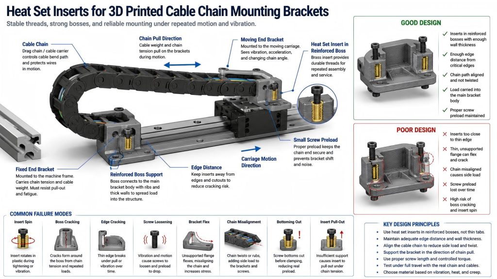
Heat set inserts can improve serviceability and thread durability in cable chain mounting brackets, but the printed geometry around the insert must still resist chain tension, bracket flex, screw preload loss, edge cracking, and vibration.
Why Cable Chain Brackets Need Careful Insert Design
A cable chain, also called a drag chain or cable carrier, guides wires, tubes, or hoses along a controlled bend path. In a 3D printed machine, one end of the cable chain may attach to a moving carriage, while the other end attaches to a fixed frame, enclosure, gantry, or bracket.
The screws holding these brackets may be small, but they are exposed to repeated motion. Each travel cycle can apply a small load to the bracket through the chain body and cable bundle. Over time, this can loosen screws, deform plastic, crack thin mounting ears, or cause inserts to spin.
The purpose of a heat set insert is not only to create reusable threads. In a cable chain mount, the insert must help maintain stable screw preload and keep the bracket aligned with the cable chain path.
Common Use Cases
3D printed cable chain mounting brackets are common in desktop machines, custom automation devices, 3D printer upgrades, CNC accessories, robotics systems, test rigs, and small production fixtures.
- drag chain fixed end brackets
- drag chain moving end brackets
- cable carrier anchor blocks
- gantry cable chain mounts
- robot axis cable chain brackets
- printer toolhead cable chain mounts
- CNC router cable carrier brackets
- linear rail cable chain supports
- electronics enclosure cable chain anchors
- prototype machine cable management brackets
For related cable management applications, see Heat Set Inserts for 3D Printed Cable Strain Relief Brackets. For related motion loading behavior, see Heat Set Inserts for 3D Printed Linear Rail End Stops.
How Cable Chain Loads Affect Heat Set Inserts
Cable chain brackets usually see moderate loads, but those loads are cyclic. The bracket may be pulled, bent, twisted, or vibrated as the chain changes position during machine travel.
Common load types include:
- chain tension from cable bundle weight
- repeated bending load from drag chain movement
- vibration from moving axes or motors
- side load from chain misalignment
- screw preload holding the bracket to a frame or carriage
- pull-out load at the fixed or moving chain end
- torsion from an offset cable chain path
- service load from removing and reinstalling the cable chain
If the insert is placed in a thin tab or near an unsupported edge, the printed bracket may crack before the insert itself fails.
Fixed End vs Moving End Brackets
A cable chain usually has two mounting conditions. The fixed end is attached to the frame or stationary structure. The moving end is attached to the carriage, toolhead, sliding axis, or moving assembly.
| Bracket Location | Main Load | Design Priority |
|---|---|---|
| Fixed end bracket | Repeated chain tension and cable weight | Prevent screw loosening, insert pull-out, and edge cracking. |
| Moving end bracket | Vibration, acceleration, and changing chain angle | Maintain alignment and prevent bracket flex. |
| Frame-mounted bracket | Screw preload and static support load | Use enough wall thickness and stable boss geometry. |
| Carriage-mounted bracket | Dynamic movement and cable chain drag | Resist vibration, torsion, and repeated motion fatigue. |
The moving end usually needs more attention because acceleration, vibration, and changing cable chain angle can make the load less predictable.
Insert Placement in Cable Chain Mounts
Insert placement should match the direction of chain force. If the cable chain pulls away from the bracket, the insert boss should not be placed so close to the edge that the load cracks through the wall.
A common mistake is designing a thin printed flange with two inserts near the edge. This may work during first assembly, but repeated chain movement can crack the flange or loosen the insert over time.
Good insert placement usually means:
- placing inserts away from thin edges and corners
- using reinforced bosses instead of thin tabs
- adding ribs between the boss and the bracket body
- supporting the cable chain in the direction of pull
- keeping enough material behind the insert
- avoiding long unsupported arms
- using a flat mounting surface under the chain end
For geometry limits, see Heat Set Insert Edge Distance Reference for 3D Printed Parts and Heat Set Insert Minimum Wall Thickness Reference for 3D Printed Parts.
Cable Chain Alignment Matters
A cable chain should follow a clean bend path. If the bracket is misaligned, the chain may twist, rub, bind, or apply side load to the mounting screws. This side load can slowly loosen screws or deform the printed bracket.
The insert cannot correct a poor cable chain path. The printed bracket should position the chain so the bending direction is smooth and the chain does not fight against the mount.
Alignment details to check include:
- chain bend direction
- distance between fixed and moving ends
- side offset between chain mounts
- available clearance through the full travel range
- cable bundle weight inside the chain
- whether the chain end sits flat on the bracket
- whether the bracket twists under motion
A well-aligned cable chain puts less stress into the insert joint. A misaligned chain turns a small screw joint into a little wrestling arena, and the plastic usually loses first.
Boss Design for Cable Chain Inserts
The insert boss should be treated as part of the cable chain load path. The boss should connect to the main bracket body so chain force can spread into the printed part instead of concentrating around one insert hole.
Useful boss design features include:
- large enough boss outside diameter
- adequate wall thickness around the insert
- ribs behind the insert boss
- fillets at boss-to-wall transitions
- wide base area under the cable chain end
- enough depth for insert seating and screw engagement
- print orientation that resists splitting under chain pull
- avoidance of sharp corners near the mounting holes
For boss design, see How to Design Bosses for Heat Set Inserts and Boss OD Ratio for Heat Set Inserts in 3D Printed Parts.
Screw Preload and Vibration
Cable chain brackets may loosen because of vibration, plastic relaxation, or repeated chain movement. A screw that feels tight during assembly may not maintain enough preload after many motion cycles.
This is especially important in PETG, nylon, or other materials that can relax under sustained clamp load. If preload drops, the bracket may begin to shift slightly. Once the bracket moves, the insert joint may see more side load and the failure can grow quickly.
Good practice includes:
- using enough screw engagement without bottoming out
- avoiding excessive tightening torque
- checking the final stack-up with the real chain end and screw
- using washers if the chain mounting hole has a small contact area
- checking bracket movement after repeated machine travel
- reinforcing the bracket against the main chain pull direction
For tightening guidance, see Heat Set Insert Torque Range Reference for 3D Printed Parts. For screw engagement behavior, see Screw Engagement Length for Heat Set Inserts in 3D Printed Parts.
Assembly Stack-Up and Bottoming Out
A cable chain mounting joint may include the printed bracket, cable chain end link, screw head, washer, insert, and sometimes a spacer or adapter plate. If the screw is too long, it may bottom out before clamping the chain end. If the screw is too short, it may not engage enough thread.
Stack-up should be checked with the actual cable chain hardware, not only the printed model. Different cable chain brands and end link styles may use different thicknesses, counterbores, or screw seat shapes.
For stack-up planning, see Heat Set Insert Assembly Stack-Up Reference for 3D Printed Parts.
Material Considerations
Material choice affects how the cable chain bracket handles vibration, bending, screw preload, and repeated motion. A stiff material can hold alignment well, but may crack if the boss is thin. A tougher material may survive impact, but may relax under preload.
| Material | Cable Chain Bracket Behavior | Insert Design Note |
|---|---|---|
| PLA | Stiff and easy to print, but can crack near thin insert bosses | Use generous boss support and avoid high-temperature locations. |
| PETG | Tougher than PLA, but may creep under sustained screw preload | Check bracket shift and screw loosening after motion cycles. |
| ABS | Useful for machine brackets with better heat tolerance | Check layer adhesion around bosses and mounting flanges. |
| ASA | Good for exposed or enclosure-mounted cable supports | Maintain edge distance and avoid thin unsupported tabs. |
| Nylon | Tough and vibration-tolerant, but may relax under preload | Use locating geometry and enough boss volume. |
| Fiber-filled materials | Stiff and stable, but can be less forgiving around sharp stress paths | Use fillets, ribs, and enough wall thickness around inserts. |
For material comparison, see PLA vs PETG vs ABS for Threaded Inserts.
Common Failure Modes
Cable chain mounting brackets often fail because small repeated loads accumulate at the insert boss or mounting flange.
- insert spin during screw tightening
- boss cracking near the chain mounting holes
- bracket flange cracking near edges
- screw preload loss after repeated motion
- chain end shifting after vibration
- printed bracket flexing during axis movement
- side load from chain misalignment
- screw bottoming out before clamping the chain end
- layer separation near the mounting boss
- insert pull-out from repeated chain tension
For related failure explanations, see Why Do Heat Set Inserts Fail Under Vibration?, Why Does Screw Preload Drop in 3D Printed Insert Joints?, and Why Do Heat Set Inserts Fail Near Edges or Corners?.
Testing Cable Chain Mounting Brackets
A cable chain bracket should be tested through the real motion range. Installing inserts successfully is not enough. The bracket must hold alignment after repeated travel cycles.
A useful test should include:
- installing inserts in the final print orientation
- assembling the bracket with the real cable chain end link
- checking screw engagement and bottom clearance
- moving the axis through its full travel range
- checking whether the chain twists or pulls sideways
- inspecting the bracket after repeated motion cycles
- checking whether screws lose preload
- checking whether the insert spins, rises, or loosens
- inspecting boss walls, flanges, and layer lines for cracks
Design Checklist
- Place inserts away from thin mounting edges and unsupported flanges.
- Use reinforced bosses connected to the main bracket body.
- Support the bracket in the direction of cable chain pull.
- Check cable chain alignment through the full travel range.
- Use enough wall thickness around the insert body.
- Use fillets and ribs near mounting bosses.
- Match screw length to the final cable chain stack-up.
- Use controlled torque to avoid insert spin or boss cracking.
- Check screw preload after repeated machine movement.
- Choose material based on vibration, creep, heat, and motion frequency.
Related Engineering Guides
- How to Choose Heat Set Inserts for 3D Printed Parts
- Heat Set Insert Hole Size Guide
- How to Design Bosses for Heat Set Inserts
- Torque Resistance of Heat Set Inserts in 3D Printed Parts
- Screw Engagement Length for Heat Set Inserts in 3D Printed Parts
- Layer Adhesion and Heat Set Insert Strength in 3D Printed Parts
Related Applications
- Heat Set Inserts for 3D Printed Cable Strain Relief Brackets
- Heat Set Inserts for 3D Printed Linear Rail End Stops
- Heat Set Inserts for High-Vibration Motor Mounting Brackets
- Heat Set Inserts in Modular Robotics Systems
FAQ
Are heat set inserts useful for 3D printed cable chain mounting brackets?
Yes. They are useful when a cable chain bracket needs reusable threads, stable screw preload, and better resistance to repeated motion, vibration, and service cycles.
How is a cable chain mount different from a cable strain relief bracket?
A cable strain relief bracket mainly reduces pulling force on wires. A cable chain mounting bracket holds the cable carrier itself and must resist repeated chain movement, vibration, alignment load, and bracket flex.
Where should inserts be placed in a cable chain bracket?
Inserts should be placed in reinforced bosses with enough wall thickness and edge distance. They should not be placed in thin unsupported tabs where chain tension can crack the printed part.
Why do cable chain brackets loosen over time?
Common causes include vibration, repeated motion, side load from chain misalignment, plastic creep, poor screw engagement, oversized pilot holes, weak boss geometry, and screw bottoming out before real clamping occurs.
Should a cable chain bracket be tested under real motion?
Yes. The bracket should be tested through the full travel range with the real cable chain, cable bundle, screws, washers, and mounting orientation. Static tightening alone does not prove long-term reliability.