
Heat Set Inserts for 3D Printed Pneumatic Manifold Covers are used when a printed manifold, air channel block, valve adapter, vacuum fixture, or low-pressure pneumatic component needs a removable cover with stable screw preload and controlled gasket compression.
A pneumatic manifold cover is not the same as a simple electronics lid. In a sealing application, the screws do more than hold a cover in place. They must apply enough clamp force to compress a gasket, keep the cover flat, and prevent air leakage along the channel or sealing path.
Heat set inserts can improve thread durability and repeated serviceability, but the printed structure must still control screw spacing, cover stiffness, boss support, sealing surface flatness, and assembly stack-up. A strong metal thread cannot compensate for an uneven cover, weak boss geometry, or poor gasket compression.
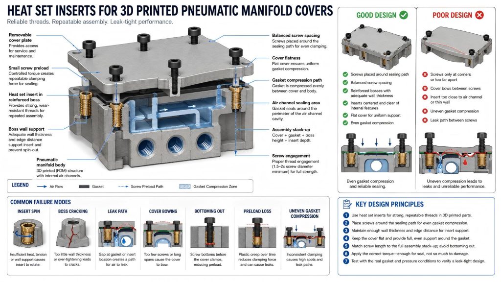
Why Pneumatic Manifold Covers Need Careful Insert Design
In a 3D printed pneumatic manifold, air passages may be printed into the body and sealed by a separate cover plate. The cover may use a gasket, O-ring cord, silicone sheet, printed groove, or soft sealing layer. Screws clamp the cover against the manifold body.
If the screw preload is uneven, the cover can lift between screws. If the screws are too far apart, the gasket may not compress consistently. If the inserts are placed too close to thin walls or air channels, the printed material may deform or crack. If the screw bottoms out in the insert before clamping the cover, the assembly may feel tight while the gasket is not actually compressed.
For pneumatic covers, insert design is part of the sealing system. The goal is not only reusable threads. The goal is controlled compression across the sealing surface.
Common Use Cases
3D printed pneumatic manifold covers are used in prototypes, test fixtures, soft robotics experiments, low-pressure automation systems, vacuum fixtures, laboratory tooling, air routing blocks, and custom machine accessories.
- low-pressure pneumatic manifold covers
- vacuum fixture cover plates
- air channel sealing plates
- valve adapter covers
- soft robotics air distribution blocks
- printed air routing manifolds
- gasketed inspection covers
- prototype pneumatic test blocks
- small automation air control modules
- replaceable cover plates for printed manifolds
For related removable cover applications, see Heat Set Inserts for Electronics Enclosure Lid Cycling and Heat Set Inserts for Battery Pack Service Covers.
How Sealing Loads Affect Heat Set Inserts
The load on a pneumatic manifold cover is different from the load on a simple mounting bracket. The screws must create clamp force, and that clamp force must be distributed across the gasket or sealing area.
Common load types include:
- screw preload compressing the cover against the manifold body
- gasket compression around air channels
- internal air pressure trying to lift the cover
- cover bending between screw locations
- plastic relaxation reducing clamp force over time
- insert pull-out from repeated service cycles
- boss cracking from overtightening
- leak paths caused by uneven cover pressure
Even low air pressure can expose poor clamp distribution. A cover may look secure, but a small gap along the sealing path can create leakage.
Insert Placement Around Sealing Paths
Insert placement should follow the sealing path. Screws should be located close enough to compress the gasket evenly, but not so close to air channels, edges, or thin walls that the printed material becomes weak.
A common mistake is placing inserts only at the four corners of a long cover. This may hold the cover down at the corners, but the center span can lift slightly. Another mistake is placing inserts too close to a gasket groove, which can distort the sealing surface or crack the wall between the insert and channel.
Good insert placement usually means:
- placing screws around the full sealing perimeter
- keeping enough distance from air channels and gasket grooves
- maintaining enough wall thickness around each insert
- avoiding inserts too close to edges or corners
- using more screws for long or narrow sealing paths
- keeping clamp points balanced across the cover
- avoiding unsupported cover spans between screws
For geometry limits, see Heat Set Insert Edge Distance Reference for 3D Printed Parts and Heat Set Insert Minimum Wall Thickness Reference for 3D Printed Parts.
Cover Flatness and Gasket Compression
A pneumatic cover must remain flat enough to compress the gasket. If the cover bends between screws, the gasket compression becomes uneven. If the manifold body warps during printing, the insert threads may be strong while the sealing surface is still unreliable.
For gasketed pneumatic covers, the most important design question is not only insert strength. It is whether the cover, gasket, and printed body create a stable sealing stack.
Useful design practices include:
- using a flat cover seating surface
- placing screws close enough to reduce cover bowing
- using a gasket groove or defined sealing land when possible
- avoiding very thin cover plates over long spans
- checking whether the screw head or washer distributes load evenly
- designing the cover so the gasket compresses before hard bottoming occurs
- keeping sealing surfaces away from rough support scars or warped print areas
The insert supports the screw thread, but the cover geometry controls whether the air stays inside. The thread is the lock, but the gasket is the quiet little gatekeeper.
Mounting Inserts vs Cover Inserts
Pneumatic manifold assemblies may use inserts in different places. Some inserts hold the cover plate down. Other inserts mount the manifold body to a machine frame, valve plate, fixture base, or enclosure wall.
| Insert Role | Main Load | Design Priority |
|---|---|---|
| Cover insert | Screw preload compressing the gasket | Maintain even clamp force and avoid boss deformation. |
| Manifold mounting insert | Fastening the manifold to a frame or fixture | Prevent bracket shift, pull-out, and vibration loosening. |
| Valve mounting insert | Small screws holding valve or fitting hardware | Maintain thread durability and avoid leaks near ports. |
| Service cover insert | Repeated cover removal and reinstallation | Prevent plastic thread wear and maintain sealing repeatability. |
Cover inserts are usually the most sensitive because they affect sealing pressure directly.
Screw Preload and Leak Risk
Pneumatic covers can leak when screw preload is too low, too uneven, or lost over time. Overtightening can also create problems. A high screw torque may crack the boss, spin the insert, crush the gasket too much, or distort the cover.
Good practice includes:
- tightening screws gradually in a balanced pattern
- avoiding excessive torque on small inserts
- using washers when the cover material is soft or thin
- checking whether screws bottom out before gasket compression
- rechecking for leaks after pressure cycling
- avoiding designs where one screw carries too much sealing load
For tightening guidance, see Heat Set Insert Torque Range Reference for 3D Printed Parts. For screw engagement behavior, see Screw Engagement Length for Heat Set Inserts in 3D Printed Parts.
Assembly Stack-Up in Pneumatic Covers
Stack-up is especially important in a gasketed cover. The final joint may include the screw head, washer, cover plate, gasket, manifold body, insert seating depth, screw engagement length, and any compression limit features.
If the screw is too long, it may bottom out in the insert before compressing the gasket. If the insert is installed too shallow, the cover may not sit flat. If the gasket is too thick or too soft, the cover may continue relaxing after assembly and lose sealing pressure.
Stack-up should be checked with the real gasket material, cover thickness, screw length, washer thickness, and insert depth.
For stack-up planning, see Heat Set Insert Assembly Stack-Up Reference for 3D Printed Parts. For insert seating behavior, see Heat Set Insert Seating Depth Reference for 3D Printed Parts.
Boss Design Around Pneumatic Cover Inserts
The boss around each insert should resist both tightening torque and long-term clamp load. If the boss deforms, the cover preload can drop. If the boss cracks, the sealing path may open near that screw location.
Useful boss design features include:
- large enough boss outside diameter
- adequate wall thickness around the insert body
- solid material between the insert and air channels
- fillets at boss-to-body transitions
- ribs or thickened pads under cover screw locations
- enough insert depth without interfering with air passages
- balanced screw spacing around the sealing perimeter
- print orientation that avoids splitting near clamp points
For boss design, see How to Design Bosses for Heat Set Inserts and Boss OD Ratio for Heat Set Inserts in 3D Printed Parts.
Material Considerations
Material choice affects sealing reliability, screw preload, creep, temperature behavior, and long-term air leakage. A material that works for a dry cover may not work well when gasket compression must remain stable.
| Material | Pneumatic Cover Behavior | Insert Design Note |
|---|---|---|
| PLA | Stiff and easy to print, but brittle and temperature-sensitive | Avoid overtightening and thin bosses near gasket grooves. |
| PETG | Tougher than PLA, but may relax under sustained screw preload | Check gasket compression and leak behavior after pressure cycling. |
| ABS | Better temperature tolerance and functional use potential | Check layer adhesion and sealing surface quality. |
| ASA | Useful for exposed or machine-adjacent pneumatic parts | Maintain boss support and avoid sharp stress paths near channels. |
| Nylon | Tough and durable, but may absorb moisture and relax under preload | Use defined sealing geometry and avoid relying only on clamp friction. |
| Fiber-filled materials | Stiff and dimensionally stable, but may print with rougher sealing surfaces | Consider surface finish and gasket compatibility carefully. |
For material comparison, see PLA vs PETG vs ABS for Threaded Inserts.
Common Failure Modes
Pneumatic manifold covers often fail through leakage before the insert visibly fails. The screw may still be tight, but the sealing pressure may not be uniform.
- air leakage between screws
- cover bowing between clamp points
- gasket under-compression near long spans
- gasket over-compression near screws
- insert spin during tightening
- boss cracking near sealing channels
- screw bottoming out before gasket compression
- preload loss from plastic creep
- cover distortion from uneven tightening
- layer separation near air channels or insert bosses
For related failure explanations, see Why Does Screw Preload Drop in 3D Printed Insert Joints?, Why Do Heat Set Inserts Fail Near Edges or Corners?, and Why Do Heat Set Inserts Fail When the Hole Is Too Large?.
Testing Pneumatic Manifold Covers
A pneumatic cover should be tested for sealing behavior, not only screw retention. A successful insert installation does not prove that the gasket is compressed evenly.
A useful test should include:
- installing inserts in the final print orientation
- assembling the cover with the real gasket and screws
- checking screw engagement and bottom clearance
- tightening screws gradually in a balanced pattern
- pressurizing the manifold at the intended working pressure
- checking for leaks along the sealing path
- repeating pressure cycles and service removal cycles
- checking whether screws lose preload after time
- inspecting bosses, gasket grooves, and layer lines for damage
- checking whether the cover remains flat after assembly
Design Checklist
- Use heat set inserts when the cover will be removed or serviced repeatedly.
- Place screws around the sealing path, not only at convenient corners.
- Maintain enough wall thickness between inserts, air channels, and edges.
- Use reinforced bosses or thickened pads under cover screw locations.
- Check that screw length does not bottom out before gasket compression.
- Use balanced screw spacing to reduce cover bowing.
- Design a clear gasket groove, sealing land, or compression surface.
- Avoid overtightening small inserts in printed bosses.
- Check preload loss in PETG, nylon, and other creep-prone materials.
- Test the cover under real pressure, gasket, screw, and service conditions.
Related Engineering Guides
- How to Choose Heat Set Inserts for 3D Printed Parts
- Heat Set Insert Hole Size Guide
- How to Design Bosses for Heat Set Inserts
- Torque Resistance of Heat Set Inserts in 3D Printed Parts
- Screw Engagement Length for Heat Set Inserts in 3D Printed Parts
- Layer Adhesion and Heat Set Insert Strength in 3D Printed Parts
Related Applications
- Heat Set Inserts for Electronics Enclosure Lid Cycling
- Heat Set Inserts for Battery Pack Service Covers
- Heat Set Inserts for Printed Jigs with Replaceable Wear Plates
- Heat Set Inserts in 3D Printed Industrial Fixtures
FAQ
Are heat set inserts useful for 3D printed pneumatic manifold covers?
Yes. They are useful when a pneumatic cover needs reusable threads, controlled screw preload, and repeatable gasket compression after service or pressure cycling.
What is the main design risk in a pneumatic manifold cover?
The main risk is uneven gasket compression. The insert may hold the screw securely, but the cover can still leak if screw spacing, cover flatness, gasket stack-up, or boss support is poor.
Can heat set inserts prevent air leaks by themselves?
No. Heat set inserts improve thread durability and screw retention, but sealing depends on the cover geometry, gasket compression, screw pattern, surface flatness, and assembly stack-up.
Where should inserts be placed around a pneumatic cover?
Inserts should be placed around the sealing path with enough spacing to compress the gasket evenly. They should also maintain enough edge distance and wall thickness from air channels, gasket grooves, and part edges.
Why does a pneumatic cover leak even when the screws feel tight?
The screws may be bottoming out, the cover may be bending between screw locations, the gasket may be unevenly compressed, or the printed material may have relaxed under preload. A tight screw does not always mean a sealed joint.