
Heat Set Inserts for 3D Printed Hinged Covers are used when a printed cover, lid, service door, access panel, or enclosure cover needs reusable metal threads around a hinge structure, latch side, removable hinge plate, or repeated-service fastening point.
A hinged cover is different from a simple removable lid. A hinged cover does not only clamp down. It rotates, opens, closes, shifts load toward the hinge side, and may create repeated bending stress around the hinge bosses. Heat set inserts can improve thread durability, but the printed geometry around the hinge must still resist screw preload, repeated motion, cover flex, alignment drift, and boss cracking.
In hinged cover designs, the insert should be treated as part of the hinge and cover load path, not only as a threaded hole.
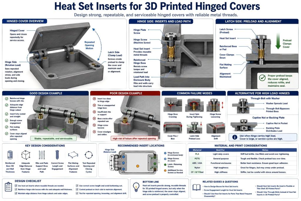
Why Hinged Covers Need Careful Insert Design
A hinged cover creates different loads on different sides of the part. The hinge side may see repeated motion, rotational force, and alignment stress. The latch side may see clamp force, preload, or snap force. The middle of the cover may flex between supports.
If the inserts are placed only where screws are convenient, the hinge may loosen, the cover may shift, or the boss may crack after repeated opening and closing.
Heat set inserts can help when a hinged cover needs repeated service, but they cannot compensate for weak hinge geometry, thin bosses, poor edge distance, or a flexible shell that bends under preload.
Common Use Cases
3D printed hinged covers are common in electronics enclosures, battery housings, control boxes, robotics covers, machine access doors, inspection panels, tool compartments, and small functional products.
- electronics enclosure hinged lids
- battery access doors
- robot service covers
- control box covers
- machine inspection panels
- sensor housing doors
- small product access covers
- fixture access lids
- replaceable hinge plates
- printed covers with latch-side screws
- fold-open maintenance panels
- hinged covers with removable hardware
For related serviceable cover applications, see Heat Set Inserts for Electronics Enclosure Lid Cycling and Heat Set Inserts for Battery Pack Service Covers.
Hinge Side vs Latch Side Loads
The hinge side and latch side of a cover usually need different design thinking. The hinge side sees repeated rotation and alignment load. The latch side often sees clamp force or closing force.
| Cover Area | Main Load | Insert Design Priority |
|---|---|---|
| Hinge side | Repeated rotation, alignment load, screw loosening | Use reinforced bosses, ribs, and good edge distance. |
| Latch side | Clamp force, closing force, preload | Control screw torque, seating depth, and cover flatness. |
| Cover corners | Edge stress and local bending | Avoid inserts too close to edges or unsupported corners. |
| Middle span | Cover flex between fastening points | Use ribs, locating lips, or additional supports if needed. |
If the hinge side is weak, the cover may remain attached but lose alignment. This is often worse than a simple loose screw because the whole cover starts behaving like a small door with a tired spine.
Where Heat Set Inserts Are Used in Hinged Covers
Heat set inserts may be used in several areas of a hinged cover assembly. The most common locations are hinge mounts, hinge plates, latch screws, and removable service fasteners.
Typical insert locations include:
- hinge screws threaded into the enclosure body
- hinge screws threaded into the cover
- removable hinge plates
- latch-side retaining screws
- access cover screws
- internal bracket screws near the hinge line
- support bosses for metal hinge hardware
- service screws used for cover replacement
The insert location should be selected based on how the cover moves and how the hinge transfers force into the printed part.
Hinge Boss Design
The hinge boss is one of the most important features in a hinged cover. It must resist screw torque during assembly and repeated stress during opening and closing.
A good hinge insert boss should provide:
- enough boss outside diameter
- enough wall thickness around the insert
- enough depth for insert seating and screw engagement
- fillets at the boss base
- ribs connecting the boss to the enclosure wall or cover body
- enough distance from edges and hinge cutouts
- a load path into the main printed structure
- print orientation that resists splitting near the hinge line
For boss geometry, see How to Design Bosses for Heat Set Inserts, Boss OD Ratio for Heat Set Inserts in 3D Printed Parts, and Heat Set Insert Minimum Wall Thickness Reference for 3D Printed Parts.
Cover Flex and Insert Reliability
A hinged cover can flex during use. If the cover is thin or flexible, tightening screws into heat set inserts may bend the cover instead of creating stable clamp force. This can cause gaps, rattling, uneven latch force, or poor alignment.
This is especially common in:
- thin electronics lids
- large covers with few screws
- PETG or nylon covers that relax under preload
- covers with a long hinge line
- covers with no internal ribs
- covers that need gasket compression
For shell bending and preload behavior, see Should Heat Set Inserts Be Used in Flexible or Thin Shell 3D Printed Parts?.
Edge Distance Near Hinges
Hinge screws are often placed close to the edge of a cover or enclosure wall. This is risky because the hinge side may see repeated rotation and side load. If the insert is too close to the edge, the boss may split toward the hinge cutout or outer wall.
Good hinge-side design usually means:
- moving inserts inward when possible
- adding local thickened pads around hinge screws
- using ribs behind hinge bosses
- avoiding narrow hinge tabs with inserts
- rounding stress transitions near hinge features
- checking edge distance from the hinge cutout and outer boundary
For edge and corner decisions, see Should Heat Set Inserts Be Used Near Edges or Corners in 3D Printed Parts? and Heat Set Insert Edge Distance Reference for 3D Printed Parts.
Screw Engagement and Hinge Hardware
Hinge hardware can create a stack-up that includes the screw head, hinge leaf, washer, cover wall, insert, and boss depth. If the screw is too short, the hinge may loosen. If the screw is too long, it may bottom out before clamping the hinge leaf.
Check the final stack-up:
- screw length
- hinge leaf thickness
- washer thickness if used
- cover or enclosure wall thickness
- insert seating depth
- available thread engagement
- bottom clearance
- whether the hinge sits flat after tightening
For screw engagement behavior, see Screw Engagement Length for Heat Set Inserts in 3D Printed Parts and Heat Set Insert Assembly Stack-Up Reference for 3D Printed Parts.
Repeated Opening and Service Cycles
A hinged cover may be opened often for maintenance, battery replacement, inspection, calibration, or electronics access. Each cycle can apply small loads to the hinge side and latch side. Over time, weak bosses may loosen or crack.
Repeated service can cause:
- hinge screws loosening
- insert spin during retightening
- boss cracking near hinge features
- cover alignment drift
- latch side preload loss
- panel rattling
- wear around hinge hardware
- cover gap after reassembly
For frequent service decisions, see Should I Use Heat Set Inserts for Parts That Need Frequent Disassembly?.
Material Considerations
Material choice affects hinge cover reliability. A stiff material may hold shape better, but may crack near hinge bosses. A tougher material may survive repeated motion, but may relax under screw preload.
| Material | Hinged Cover Behavior | Insert Design Note |
|---|---|---|
| PLA | Stiff, but brittle near hinge bosses and thin corners | Use generous fillets, ribs, and avoid overtightening. |
| PETG | Tougher and more flexible, but may relax under preload | Check hinge screw preload and cover alignment over time. |
| ABS / ASA | Useful for functional covers with better heat tolerance | Control layer adhesion and hinge boss geometry. |
| Nylon | Tough and flexible, but may creep under clamp load | Use locating geometry and avoid relying only on screw preload. |
| Fiber-filled materials | Stiff and stable, but can concentrate stress near hinge bosses | Use fillets, smooth transitions, and reinforced hinge zones. |
For material comparison, see PLA vs PETG vs ABS for Threaded Inserts and Layer Adhesion and Heat Set Insert Strength in 3D Printed Parts.
When Through-Bolts or Captive Nuts May Be Better
Heat set inserts are useful for serviceable hinge screws, but they may not be enough if the hinge carries high load, impact, or repeated opening force. In those cases, through-bolts, washers, captive nuts, or backing plates can spread load more effectively.
Consider through-bolts or captive nuts when:
- the hinge carries the weight of a large cover
- the hinge side is thin or flexible
- the cover is opened very frequently
- the hinge sees vibration or impact
- the insert would be too close to the edge
- the boss cannot be reinforced enough
- failure would damage the assembly
For through-bolt decisions, see Should I Use Through-Bolts Instead of Heat Set Inserts in 3D Printed Parts?.
Common Failure Modes
Hinged covers often fail because the hinge side creates repeated stress near small screw bosses. The insert may remain threaded, but the printed material around it may loosen or crack.
- hinge boss cracking
- insert spin during hinge screw tightening
- hinge screws loosening after repeated opening
- cover misalignment
- latch side preload loss
- thin cover bowing
- edge cracking near hinge cutouts
- boss splitting along layer lines
- screw bottoming out before hinge clamping
- rattle or gap after service cycles
For related failure explanations, see Why Do Bosses Crack Around Heat Set Inserts?, Why Do Heat Set Inserts Spin in 3D Printed Parts?, and Why Does Screw Preload Drop in 3D Printed Insert Joints?.
Design Checklist
- Use heat set inserts where hinge screws or latch screws need reusable metal threads.
- Reinforce hinge-side bosses with ribs, pads, or thicker geometry.
- Keep inserts away from hinge cutout edges and unsupported corners.
- Check screw length against hinge hardware and insert seating depth.
- Use locating features so the cover returns to the same position after service.
- Control screw torque to avoid insert spin or boss cracking.
- Use washers, backing plates, or through-bolts for higher hinge loads.
- Test repeated opening and closing with the final material and hardware.
- Check for cover bowing, hinge loosening, and latch-side gaps.
- Use material and print orientation that support the hinge load direction.
Related Engineering Guides
- How to Choose Heat Set Inserts for 3D Printed Parts
- How to Design Bosses for Heat Set Inserts
- Screw Engagement Length for Heat Set Inserts in 3D Printed Parts
- Torque Resistance of Heat Set Inserts in 3D Printed Parts
- PLA vs PETG vs ABS for Threaded Inserts
- Layer Adhesion and Heat Set Insert Strength in 3D Printed Parts
Related Selection Questions
- Should I Use Heat Set Inserts for Parts That Need Frequent Disassembly?
- Should Heat Set Inserts Be Used in Flexible or Thin Shell 3D Printed Parts?
- Should I Use Through-Bolts Instead of Heat Set Inserts in 3D Printed Parts?
Related Applications
- Heat Set Inserts for Electronics Enclosure Lid Cycling
- Heat Set Inserts for Battery Pack Service Covers
- Heat Set Inserts for Robot Joint Service Panels
FAQ
Are heat set inserts useful for 3D printed hinged covers?
Yes. They are useful when hinge screws, latch screws, or service screws need reusable metal threads. The hinge-side boss still needs reinforcement because the cover creates repeated motion and alignment loads.
Where should inserts be placed in a hinged cover?
Common insert locations include hinge screw bosses, removable hinge plates, latch-side screws, and service cover fasteners. Inserts should not be placed too close to hinge cutout edges or unsupported corners.
Why do hinged cover inserts loosen?
They may loosen because of repeated opening, screw preload loss, hinge-side flex, boss cracking, insert spin, poor screw engagement, or cover alignment drift.
Should hinged covers use through-bolts instead of inserts?
Through-bolts may be better when the hinge carries high load, the cover is large, the boss is thin, or the hinge side sees vibration or impact. Inserts are better for serviceable internal threads when the boss is strong enough.
How should hinged cover bosses be reinforced?
Use larger boss diameter, adequate wall thickness, ribs, fillets, local pads, edge distance, and a load path into the main cover or enclosure body.