
Should heat set inserts be used near edges or corners in 3D printed parts? Heat set inserts can be used near edges or corners only when the printed part has enough edge distance, wall thickness, boss diameter, and load path support. In most functional parts, inserts should not be placed too close to an edge, corner, slot, cutout, or thin flange unless the area is locally reinforced.
An insert near an edge has less plastic around it. That means less material to resist installation heat, radial expansion, screw torque, pull-out load, and preload stress. A corner location can be even more sensitive because stress may concentrate along two nearby free edges.
The question is not whether an insert can physically fit near an edge. The real question is whether the printed geometry around that edge can support the insert after installation, screw tightening, service cycles, and real loading.
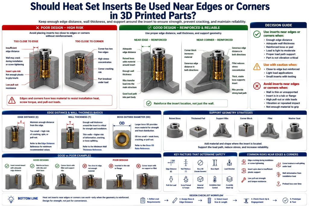
Short Answer
Avoid placing heat set inserts too close to edges or corners unless the insert area is reinforced. Use enough edge distance, wall thickness, boss support, and load path geometry before trusting the joint.
| Insert Location | Risk Level | Recommended Design Action |
|---|---|---|
| Centered in a reinforced boss | Low | Usually preferred for functional parts. |
| Near one edge with enough wall thickness | Moderate | Check edge distance, boss OD, screw load, and material. |
| Near a corner | High | Add corner block, pad, rib, or move the insert inward. |
| In a thin tab or flange | High | Usually redesign unless the load is very light. |
| Near a slot, cutout, or sharp inside corner | High | Add material or move the insert away from the stress path. |
Why Edge Distance Matters
Edge distance is the amount of printed material between the insert hole and the nearest outside edge of the part. If that distance is too small, the insert has less plastic to grip and less structure to resist load.
When a heat set insert is installed, the surrounding plastic softens and flows around the insert knurls. If the insert is too close to an edge, the softened plastic may bulge outward, crack, split, or leave the insert with weak support on one side.
Low edge distance can cause:
- edge cracking during installation
- insert spin during screw tightening
- boss splitting toward the nearest edge
- reduced pull-out strength
- reduced torque resistance
- wall deformation from installation heat
- preload loss after assembly
- part breakout under load
For edge planning, see Heat Set Insert Edge Distance Reference for 3D Printed Parts.
Why Corners Are More Sensitive Than Straight Edges
A corner can be more sensitive than a straight edge because the insert may be close to two free edges at the same time. This reduces support in more than one direction and can concentrate stress during installation or screw tightening.
Corner inserts are especially risky when the corner is:
- thin
- sharp
- unsupported
- near a slot or cutout
- part of a flexible flange
- loaded sideways
- used for repeated assembly
- printed with weak layer orientation
A corner insert can work, but the corner should be treated as a reinforced mounting block, not just a convenient place for a screw hole.
When Inserts Near Edges May Be Acceptable
Heat set inserts may be acceptable near edges when the edge area is thick, reinforced, and lightly loaded. The insert location should have enough plastic around the hole and enough structural support behind the load direction.
Edge-adjacent inserts may work when:
- the insert is not too close to the edge
- the boss has enough outside diameter
- there is enough wall thickness around the insert
- the screw load is light to moderate
- the part is not heavily vibration-loaded
- the edge area is reinforced with ribs or pads
- the insert is not installed into a thin tab
- the load path transfers into the main body of the part
- the joint has been tested with the final material and screw
For boss sizing, see How to Design Bosses for Heat Set Inserts and Boss OD Ratio for Heat Set Inserts in 3D Printed Parts.
When Inserts Near Edges Should Be Avoided
Heat set inserts should usually be avoided near edges when the surrounding plastic cannot support the insert in all important directions. If the nearest edge is thin, unsupported, or part of a narrow tab, the insert may fail even if it installs cleanly.
Avoid edge-adjacent inserts when:
- the insert is very close to the part boundary
- the wall between insert and edge is thin
- the insert sits in a narrow tab or flange
- the joint carries structural load
- the screw needs high preload
- the part sees vibration or impact
- the load pulls toward the edge
- the corner has no fillet, rib, or thickened block
- the material is brittle or printed with weak layer adhesion
- the insert will be removed and reinstalled many times
For related failure behavior, see Why Do Heat Set Inserts Fail Near Edges or Corners?.
Load Direction Matters
Edge distance should be judged together with load direction. An insert near an edge is more likely to fail if the screw load, pull-out load, or side load points toward that edge.
For example, if a bracket is pulled outward and the insert is close to the outer edge, the load may break through the shortest wall path. If the same insert is supported by a rib or thick body behind the load direction, it may perform better.
Check whether the load is mainly:
- axial pull-out
- screw tightening torque
- side load
- vibration
- impact
- repeated assembly preload
- clamp force across a cover or bracket
The insert should be placed so the printed material carries load into the main body, not through a thin edge wall.
Boss Design Near Edges and Corners
If an insert must be near an edge or corner, the boss should be designed as a reinforced feature. The goal is to give the insert enough local plastic support while spreading load into the main printed body.
Useful reinforcement strategies include:
- moving the insert inward when possible
- increasing boss outside diameter
- adding a local thickened pad
- adding ribs behind the boss
- using a corner block instead of a thin corner tab
- rounding sharp corner transitions
- adding fillets where the boss meets the wall
- avoiding narrow unsupported ears
- using a washer or larger clamp surface when needed
- aligning the boss with the real load path
A good edge-adjacent boss should look deliberate. A risky one looks like the insert was squeezed into the last scrap of plastic left on the map.
Wall Thickness Still Matters
Edge distance and wall thickness work together. Even if the insert is not extremely close to the edge, the wall can still crack if there is not enough thickness around the insert body.
This is especially important in thin enclosure lips, mounting tabs, small flanges, and compact brackets. A heat set insert needs enough material around the full diameter, not only enough distance in one direction.
For wall thickness planning, see Heat Set Insert Minimum Wall Thickness Reference for 3D Printed Parts and Should I Use Heat Set Inserts in Thin-Wall 3D Printed Parts?.
Small Inserts Are Not a Complete Solution
Using a smaller insert can reduce the required boss size, but it does not remove the need for edge distance. An M2 or M2.5 insert can still crack a small corner if the boss is too thin or too close to the part boundary.
Smaller inserts may help when:
- the load is light
- space is limited
- the boss still has enough wall thickness
- the screw does not need high preload
- the part will not see heavy vibration or repeated service
But smaller inserts should not be used as a shortcut for weak geometry. If the insert is close enough to the edge that the wall behaves like a shell, the better answer is usually to redesign the boss.
For small insert selection, see Should I Use M2.5 or M3 Heat Set Inserts in 3D Printed Parts?.
Short Inserts May Reduce Edge Risk
A shorter insert may be safer near an edge if the part has limited depth or the surrounding wall is thin. Shorter inserts require less seating depth and usually introduce less heat into the boss.
However, a short insert also provides less thread engagement and lower pull-out margin. It should only be used when the load requirement allows it.
Short inserts may help when:
- the boss is shallow
- the edge area is compact
- the load is light to moderate
- there is limited clearance below the insert
- installation heat must be minimized
For length selection, see Should I Use Short or Long Heat Set Inserts in 3D Printed Parts? and Short vs Long Heat Set Inserts for 3D Printed Parts.
Material Choice Changes Edge Risk
Material behavior affects whether an edge-adjacent insert survives. Brittle materials may crack near edges. Creep-prone materials may lose preload and shift under load. Weak layer adhesion can make an insert split out along the print layers.
| Material | Edge/Corners Insert Risk | Design Note |
|---|---|---|
| PLA | Can crack near edges and sharp corners | Use generous edge distance, fillets, and avoid overtightening. |
| PETG | Tougher, but may deform or lose preload near thin edges | Use reinforced bosses and check screw preload over time. |
| ABS / ASA | Can work well with good layer adhesion and enough material | Control installation heat and avoid unsupported corner tabs. |
| Nylon | Tough, but may creep under preload | Use broad load paths and avoid relying only on screw friction. |
| Fiber-filled materials | Stiff, but can be less forgiving near sharp corners | Use fillets, ribs, and careful pilot hole testing. |
For material comparison, see PLA vs PETG vs ABS for Threaded Inserts and Layer Adhesion and Heat Set Insert Strength in 3D Printed Parts.
Installation Heat Can Break Edge Features
Edges and corners can distort more easily during insert installation because there is less surrounding plastic to absorb and spread the heat. If the insert is overheated or pushed too hard, the edge may bulge, crack, or soften unevenly.
Common heat-related edge risks include:
- edge wall bulging outward
- corner cracking during insertion
- insert tilting toward the open edge
- plastic breaking through the side
- seating depth becoming inconsistent
- nearby thin features warping
- hole becoming oversized after overheating
For installation control, see Heat Set Insert Installation Temperature for 3D Printed Parts and Heat Set Insert Seating Depth Reference for 3D Printed Parts.
Screw Preload Near Edges
Screw preload can pull or bend a weak edge feature even after the insert has installed successfully. This is common in thin covers, small tabs, enclosure corners, and lightweight brackets.
The screw may feel tight, but the printed edge may slowly deform, especially in PETG, nylon, or other materials that relax under clamp load.
To reduce preload problems:
- avoid overtightening
- use washers when appropriate
- increase boss support
- add ribs behind edge-mounted bosses
- move the insert inward if possible
- check screw length and bottoming risk
- test preload after service cycles
For preload behavior, see Why Does Screw Preload Drop in 3D Printed Insert Joints? and Heat Set Insert Torque Range Reference for 3D Printed Parts.
Common Mistakes
- placing inserts too close to the part edge
- using a corner as a screw point without reinforcement
- putting inserts into thin tabs or flanges
- ignoring load direction toward the edge
- using a larger insert without increasing boss size
- choosing a small insert but leaving too little wall thickness
- overheating edge-adjacent bosses
- overtightening screws near corners
- not checking screw bottoming and stack-up
- assuming a clean installation means the edge is strong enough
For related failure behavior, see Why Do Bosses Crack Around Heat Set Inserts?, Why Do Heat Set Inserts Fail When the Hole Is Too Small?, and Why Do Heat Set Inserts Fail When the Hole Is Too Large?.
Practical Decision Rule
Use this simple rule:
- Avoid edge-adjacent inserts when the insert can be moved inward.
- Use edge-adjacent inserts only when there is enough edge distance, wall thickness, and boss support.
- Do not place inserts in thin corners, unsupported tabs, or narrow flanges without reinforcement.
- Add ribs, pads, fillets, or corner blocks when the insert must stay near an edge.
- Test the real material, screw torque, and load direction before using the part functionally.
A heat set insert near an edge is not automatically wrong. But the edge must stop being a fragile border and become a reinforced structural zone.
Related Engineering Guides
- How to Choose Heat Set Inserts for 3D Printed Parts
- Heat Set Insert Hole Size Guide
- How to Design Bosses for Heat Set Inserts
- Screw Engagement Length for Heat Set Inserts in 3D Printed Parts
- Torque Resistance of Heat Set Inserts in 3D Printed Parts
- Heat Set Insert Installation Temperature for 3D Printed Parts
Related Selection Questions
- Should I Use Heat Set Inserts in Thin-Wall 3D Printed Parts?
- Should I Use Short or Long Heat Set Inserts in 3D Printed Parts?
- Should I Use M2.5 or M3 Heat Set Inserts in 3D Printed Parts?
Related Failure Questions
- Why Do Heat Set Inserts Fail Near Edges or Corners?
- Why Do Heat Set Inserts Fail in Thin Wall 3D Printed Parts?
- Why Do Bosses Crack Around Heat Set Inserts?
- Why Do Heat Set Inserts Fail When the Hole Is Too Small?
- Why Do Heat Set Inserts Fail When the Hole Is Too Large?
Related References
- Heat Set Insert Edge Distance Reference for 3D Printed Parts
- Heat Set Insert Minimum Wall Thickness Reference for 3D Printed Parts
- Boss OD Ratio for Heat Set Inserts in 3D Printed Parts
- Heat Set Insert Seating Depth Reference for 3D Printed Parts
- Heat Set Insert Assembly Stack-Up Reference for 3D Printed Parts
FAQ
Can heat set inserts be placed near the edge of a 3D printed part?
Yes, but only when there is enough edge distance, wall thickness, boss support, and load path reinforcement. Inserts placed too close to edges can crack, spin, pull out, or break through the side wall.
Are heat set inserts near corners more risky?
Yes. Corners are often more sensitive because the insert may be close to two free edges at the same time. A corner insert should usually be supported with a thicker corner block, rib, pad, or fillet.
What should I do if the insert must be near an edge?
Add local reinforcement. Use a larger boss, thickened pad, support rib, corner block, fillet, or washer seat. If possible, move the insert inward so the load transfers into the main body of the part.
Can I use a smaller insert near an edge?
Sometimes, but a smaller insert still needs enough surrounding plastic. Smaller size may reduce space requirements, but it does not replace proper edge distance, wall thickness, and boss support.
What is the main risk of placing inserts too close to edges?
The main risk is that the printed material between the insert and edge is too weak to resist installation heat, screw torque, pull-out load, or preload. This can cause edge cracking, insert spin, boss splitting, or part breakout.